Showing posts with label Routing Protocols. Show all posts

Friday, December 5, 2008

OSPF: Peering Basics (IPExpert VoD) - Part I

Ok, it has been a while I don´t post anything, but believe me, it´s not because I don´t want too... I´m really away from everything due to a huge project to implement before christmas, hopefully!

That means... I do have "ocasional"  internet access (like, 1h every 5 days, can you believe that?! Me neither! It´s really difficult for a "Internet Addicted" guy like me)!!!

Anyway... That´s why I´m a bit away from all the news (I can see some exciting news regarding EverythingIE and Dynamips support from IPExpert), also a new online vClass from them, and a new introductory class from Internetwork Expert! Cool! As always, the most they try to be better than the other, we win! :) Wonderful man!

Also, Joe, I saw your email - sorry for taking so long to reply, but I´ll do it soon! Very NICE diagram and observations there! Sorry for taking too long to reply it to you, but I´ll do it soon! :S

So... let´s get a bit more technical, into OSPF, those are some notes, personal understandings and mostly the instructions, tips and advices from IPExpert VoD (awesome material). OSPF is splitted in several parts on those VoD starting with peering basics, which in my opinion, makes sense, why implement other features like security before having full reachability ?! Insane if you ask me! That means, when you get into the OSPF section, don´t worry about authentication, or area type, or things like that! Get the basics peering up and functional! Period!

That means, assign the correct router/interfaces in the correct areas, like area 0, area 1, and forget everything else, like stub, nssa, and others! Take one step at a time!

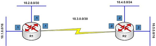
Look at your diagram and check the issues you could have to peer between the routers using OSPF... For sure the first thing that will cause us problems will be OSPF and Frame-Relay...

Oh yeah... just to remember, the Frame-Relay world has 3 different Frame-Relay interface types: Physical, Multipoint and point-to-point.

Now... as far as OSPF is concerned, we have 5 different network types. Out of that, either Multipoint and Physical Frame-Relay interfaces are both going to default to an OSPF Non-Broadcast Network Type.

On the other hand, the Point-to-Point Frame-Relay subinterface is going to default to a Point-to-Point Network Type in OSPF.

That can lead us to some mismatches, depending on the frame-relay network setup and topology. As Scott likes to say, little things to be looking at, but very important! :)

Match your network and interface types together! First of all, timers may not match if you try to mix different interface types!

There´s also the DR Router! We must take care to make our HUB router the DR! Also, if running over a Non-Broadcast link, don´t forget the broadcast parameter in the frame-relay maps, to have OSPF actually "working" on your network (even better, on your exam!). One piece of advice is, on a point-to-point subinterface this is enabled by default.

There are some tools (AKA debug) that we can use to check this "broadcast"  issue, like debug ip packet, if you get encapsulation failed, that pretty much tells you that there´s something missing (that could be the broadcast parameter in your maps, or some other kind of little thing we usually forget about).

Also, keep in mind the neighbor command! They may forbidden you from changing the network types, and things like that, we can always use the neighbor command to try to achieve neighbor relationship.

You MUST read your exam carefully and understand how it´s worded! It might tell you: don´t change the network type on the spokes, or on the HUB change to a network type other than broadcast! At the VoD Scott suggest us to start looking at the details, looking at the things that match, looking at the things that NEEDS to match in order to perform peer! Start thinking and choosing how you´re going to do stuff! A great advice!

Any interface that is Point-to-Something does NOT elect a DR, keep that in mind! But, Broadcast and Non-Broadcast will!

Broadcast - Elects a DR, and it has what we call fast timers,  10/40 sec (hello/dead) timers.

Non-Broadcast - Elects a DR, but has slow timers, 30/120 sec! It also works in the unicast fashion,  it "must" have the neighbor command! Very important! It MUST have it! In order to actually operate!

But the real question is: Can we mix and match those types?! If our spokes are Non-Broadcast, can we make the HUB Broadcast?! Sure! Absolutely! We´ll have to change timers, they need to match, either fast or slow, doesn´t matter, but they have to be the same at each end.

Also... the neighbor command... where to put it on this situation?! On this "scenario" the neighbor command goes into the spokes, even knowing that we may normally have to put them on the hub! If your HUB is in Broadcast type, the neighbor command is not accepted!

As long as the timers match, and your choices about the DR, we´re good to go!

Point-to-Point and Point-to-Multipoint, same thing, you can mix and match those if I want too, just adjusting timers!

Point-to-Multipoint Non-Broadcast (Cisco Proprietary) It assumes the same type of idea the point-to-multipoint does, uses the same slow timers and stuff, but, it must use unicast packets, that means, it uses the neighbor command ...

Now, in order to form a peering relationshipe, there are a number of things that needs to match!

Timers for example, it needs to match! We can change it! Like the OSPF Hello Timer, if we change the Hello Timer, the Dead Timer automatically changes (by the way, the Dead Timer can also be changed independently, to achieve any weird task if needed)!

Other things that must match:

MTU Size must match!

Area ID must match! That makes sense! We can´t peer an Area 0 guy with an Area 1 guy! :)

Stub Flag must match! Now, this highlights a very important rule in OSPF, one of the OSPF rules is that everybody in an Area must have the same database information! Well... what the Stub flag does?! It says a variaty of things, but it´ll tell your router it can´t have external routes as an example, what about the other router in the area, if it "wants" to have external routes!? Things are not going to work very well in this situation! Everybody MUST agree about the Stub Flag!

The same applies to Netmask! It´s important to know "we´re" all in the same network in there! There are some exceptions with Virtual-Links and Point-to-Point interfaces, don´t need to worry about that part, but, as we go through, all of these things have to match!

One very important thing is missing out of this list! That will be the DR!

Technically you can peer "something" that requires a DR with "something" that doesn´t requires a DR. However, things will be all messed up if we do that! In the DR world, somebody believes they´re in charge, and they´re the ones who can announce the routes officially!

On the non-DR network everybody has the right to announce routes, and that will mess up all of your database and reachability.

So, even knowing the DR is not a poart of the list here, you do have to match and agree to who is or is not the DR!

The neighbor command (we´re talking about it very much, don´t you think?!), is basically used when I can´t use multicast in order to get to the other side!

Technically it´s only necessary in one side of the connection, so, in a Hub and Spoke network I would probably use my Hub to put this. One place, put all the neighbors, keep life simple! But, this is not necessary! You can do it in the spokes if you want! You can do in both if you want! No big deal! But you have to have the neighbor command some place in order to initiate the conversation!

So, in our example, making the HUB Broadcast, and the Spokes Non-Broadcast, the neighbor command HAS to go on the spokes, the broadcast guy (the HUB in this situation) won´t even accept the neighbor command!

Your HUB will be sending out it´s multicast frames, no one will be talking back to it, and them, it gets an unicast from one of the spokes and says "Oh, ok! This is how you wanna talk?! Not a problem" and it´ll respond to that spoke.

Back in our example scenario... the neighbor command MUST be used in every spoke in order to trully operate! Once each of them initiates the unicast conversation the HUB will reply just fine, and everything will be working great! It takes a while, like a couple minutes, but it´ll happen just fine!

And that´s just the neighbor command!

Next post we´ll talk about the other features presented in the VoD, like loopbacks, DR, and MTU... I really gotta go now!

Nice weekend to everybody, and don´t ever give up! Keep going on your studies (check this wonderful post from Ethan Banks about this).

Cheers!

Tuesday, November 4, 2008

How to check your Diagram for potential Routing Loops

One of the most challenging tasks in the CCIE Lab is how to deal with routing loops, specially when dealing with redistribution. I still working my way through it and I still missing alot (any comments, thoughts, suggestions will be welcome!).

Anyway... I will not deal here (in this specific post of course) with the details about redistribution, and anything else. I will just check the topology for potential routing loops, and redistribution points! (and please, correct me if I´m wrong, ok?!).

Let´s check this diagram from IPExpert Workbook Vol. 3 - Lab. 1 (this Lab 1 is available for download at IPExpert Website, go get yours).

image

To keep things simple, forget that R4 Serial connection is also connected to R5 through Frame-Relay network, just pretend it is connected direct through Serial Interfaces, ok?!

So we have EIGRP, OSPF and RIP all over our topology, and guess which protocol was choosen to be in the Frame-Relay network?! Yes, you´re right! OSPF!

Anyway, checking it a little deeper, we can see that routers BB2, R4, R5 and R2 have direct connections and those routers are using RIP. Also, R1 and SW1 are using RIP between them! That should not take too long to be configured (depending on what is being asked), but probably not very challenge.

In the EIGRP "world" we have BB1, R6, R7 and R9 routers. Note that there are two interfaces between R6 and R9. Again, that also should not take too long to be configured depending on what the task is asking and the restrictions applied!

Now... OSPF! It´s being used between R2, R5 and R6 in the OSPF Area 256, and between R1 and R2 in OSPF Area 12.

Now that we checked the IPv4 IGP Routing Protocols in this diagram, we also need to verify it for potential Routing Loops. Check the bellow drawing:

image

Starting from BB2, to the top of the topology, we can see two loops in our network. One represented by the "ORANGE" arrows and the other by the "RED" arrows.

First, let´s analyze the loop in "ORANGE" between R6 and R9. It´s inside EIGRP AS679. So, this loop is "contained" inside one routing protocol. The routing protocol will deal with it. No worries!

Now... the loop between R2 and R5 (represented by the "RED" arrows). This one involves two distinct routing protocols! So we must take care when doing redistribution between those routing domains, either by using different Administrative Distance (AD), route-maps, access-list or any tool that we´re allowed to use to avoid it!

Regarding the redistribution points... we´ll need to redistribute routes in R2, R6 and "maybe" in R1, it´ll all depend on the connections!

Just keep in mind that, when dealing with routing loops we can have situations like:

Routing Loop with a single IGP: That kind of situation will not create a routing loop when redistribution is performed, because, it´ll be filtered by the IGP in use.

Routing Loops  with two or more IGPs:  In  this situation we´ll need to take care off "manually", using filters, maps, access-lists, and other tools when dealing with redistribution, avoiding for example that RIP domain learn OSPF routes, and them send those routes back to the OSPF domain!

This analysis seens simple, but try to do it in some different diagrams on your own to get more practice, I´ll do the same!

Later we´ll discuss the details involving the redistribution and the IGPs!

Cheers!

Wednesday, October 22, 2008

OSPF Virtual-Links

OSPF Virtual-Links are used to extend Area 0 to routers without direct connection to OSPF Area 0.

A diagram will help us to understand this requirement a bit better:

OSPF Virtual Link-C1

The link between R1 F0/0 and R2 F0/0 belongs to the Backbone Area, or Area 0. The Frame-Relay connection between R2 S0/0 and R3 S0/0 belongs to the OSPF Area 1. As far as R2 has a direct connection to Area 0 (through it´s F0/0 interface) no Virtual-Links are needed.

BUT, for example, if we create a Loopback Interface in R3, and place this Loopback Interface in OSPF Area 2, what will happen?!

R3 doesn´t have any connections to Area 0, it has connections to OSPF Areas 1 and 2, but not Area 0. Check this new diagram including the newly created Loopback Interface in R3:      

OSPF Virtual Link - C2

Hmmm... This situation will require the use of Virtual-Links between R3 and R2 using Area 1 as a "connection" to Area 0. In situations like this, where the router (in our case R3) has two or more interfaces in different areas, and none of those interfaces belongs to Area 0, we´ll need to use an OSPF Virtual-Link.

You may ask yourself:  why R3 S0/0 in Area 1 doesn´t need a Virtual-Link connection also?! It´s on the same router as the Area 2 Loopback Interface, so why R3´s Loopback in Area 2 need a Virtual-Link connection, but R3´s S0/0 interface in Area 1 doesn´t?!

The answer is simple, R3 is direct connected to R2 using Area 1, and R2 is connected to Area 0, so it´ll get advertised due to R2 connections! ;)

Without Virtual-Links Area 2 (in this situation) would never get advertised to either R2 and R1!

First, let´s go ahead and configure all routers according to our diagram (except by the Virtual-Links):

R1:

int f0/0
ip address 192.168.10.1 255.255.255.0
no shut
!
router ospf 1
router-id 1.1.1.1
network 192.168.10.0 0.0.0.255 area 0

R2:

int f0/0
ip address 192.168.10.2 255.255.255.0
no shut
!
int s0/0
encapsulation frame-relay
ip address 192.168.11.2 255.255.255.0
frame-relay map ip 192.168.11.3 203 broadcast
no shut
!
router ospf 1
router-id 2.2.2.2
network 192.168.10.0 0.0.0.255 area 0
network 192.168.11.0 0.0.0.255 area 1
neighbor 192.168.11.2

R3:

interface loopback 2
ip address 192.168.12.3 255.255.255.0
!
interface serial 0/0
encapsulation frame-relay
ip address 192.168.11.3 255.255.255.0
frame-relay map ip 192.168.11.2 302 broadcast
no shut
!
router ospf 1
router-id 3.3.3.3
network 192.168.11.0 0.0.0.255 area 1
network 192.168.12.0 0.0.0.255 area 2
neighbor 192.168.11.2

Ok! The above configuration is done, let´s check the OSPF Neighbor Relationship and the IP Routing Tables of our routers:

R1:

R1(config)#do sh ip route

Codes: C - connected, S - static, R - RIP, M - mobile, B - BGP
D - EIGRP, EX - EIGRP external, O - OSPF, IA - OSPF inter area
N1 - OSPF NSSA external type 1, N2 - OSPF NSSA external type 2
E1 - OSPF external type 1, E2 - OSPF external type 2
i-IS-IS, su-IS-IS summary, L1-IS-IS level-1, L2-IS-IS level-2
ia-IS-IS inter area, *-candidate default,U-per-user static route
o - ODR, P - periodic downloaded static route

Gateway of last resort is not set

C    192.168.10.0/24 is directly connected, Ethernet0/0
O IA 192.168.11.0/24 [110/74] via 192.168.10.2, 00:00:00, Ethernet0/0

R1(config)#do sh ip ospf neig

Neighbor ID  Pri State    Dead Time  Address        Interface
2.2.2.2       1  FULL/DR  00:00:38   192.168.10.2   Ethernet0/0

=================================================================

R2:

R2(config)#do sh ip route

Codes: C - connected, S - static, R - RIP, M - mobile, B - BGP
D - EIGRP, EX - EIGRP external, O - OSPF, IA - OSPF inter area
N1 - OSPF NSSA external type 1, N2 - OSPF NSSA external type 2
E1 - OSPF external type 1, E2 - OSPF external type 2
i-IS-IS, su-IS-IS summary, L1-IS-IS level-1, L2-IS-IS level-2
ia-IS-IS inter area, *-candidate default,U-per-user static route
o - ODR, P - periodic downloaded static route

Gateway of last resort is not set

C    192.168.10.0/24 is directly connected, Ethernet0/0
C    192.168.11.0/24 is directly connected, Serial1/0

R2(config)#do sh ip ospf neig

Neighbor ID  Pri State    Dead Time  Address        Interface
1.1.1.1       1  FULL/BDR 00:00:30   192.168.10.1   Ethernet0/0
3.3.3.3       1  FULL/DR  00:01:43   192.168.11.3   Serial1/0

=================================================================

R3:

R3#sh ip route
Codes: C - connected, S - static, R - RIP, M - mobile, B - BGP
D - EIGRP, EX - EIGRP external, O - OSPF, IA - OSPF inter area
N1 - OSPF NSSA external type 1, N2 - OSPF NSSA external type 2
E1 - OSPF external type 1, E2 - OSPF external type 2
i-IS-IS, su-IS-IS summary, L1-IS-IS level-1, L2-IS-IS level-2
ia-IS-IS inter area, *-candidate default,U-per-user static route
o - ODR, P - periodic downloaded static route

Gateway of last resort is not set

C    192.168.12.0/24 is directly connected, Loopback2
O IA 192.168.10.0/24 [110/74]via 192.168.11.2,00:00:24,Serial1/0
C    192.168.11.0/24 is directly connected, Serial1/0

R3#sh ip ospf neig

Neighbor ID  Pri State        Dead Time  Address      Interface
2.2.2.2       1  FULL/DROTHER 00:01:56   192.168.11.2 Serial1/0

See?! Neither R1 and R2 have the 192.168.12.0/24 Network from Area 2! That´s because R3 is not directly connected to Area 0! To solve that, we´ll need to configure a Virtual-Link between R2 and R3 using Area 1 as a "connection" to Area 0.

The command to do that is: area <area-id> virtual-link <rid of the router in the other end>, for example: R3 will have the following command added to it´s configuration: area 1 virtual-link 2.2.2.2 . The same command (just changing R2´s rid by R3´s rid) needs to be configured in R2. To make things a little bit easier, here follows the configuration:

R2:

router ospf 1
area 1 virtual-link 3.3.3.3

R3:

router ospf 1
area 1 virtual-link 2.2.2.2

Oh yeah! If you´re unsure about the Router ID (rid) of the router, just issue a show ip ospf command and it´ll show you the Router ID, see below:

R3(config)#do sh ip ospf
 Routing Process "ospf 1" with ID 3.3.3.3
Supports only single TOS(TOS0) routes
Supports opaque LSA
Supports Link-local Signaling (LLS)
Supports area transit capability
Initial SPF schedule delay 5000 msecs

<output omitted>

Now, with the virtual-link configured between R2 and R3, let´s check again the OSPF Neighbor Relationship and the IP Routing Table of all our three routers:

R1:

R1(config)#do sh ip route

Codes: C - connected, S - static, R - RIP, M - mobile, B - BGP
D - EIGRP, EX - EIGRP external, O - OSPF, IA - OSPF inter area
N1 - OSPF NSSA external type 1, N2 - OSPF NSSA external type 2
E1 - OSPF external type 1, E2 - OSPF external type 2
i-IS-IS, su-IS-IS summary, L1-IS-IS level-1, L2-IS-IS level-2
ia-IS-IS inter area, *-candidate default,U-per-user static route
o - ODR, P - periodic downloaded static route

Gateway of last resort is not set

     192.168.12.0/32 is subnetted, 1 subnets
O IA    192.168.12.3 [110/75] via 192.168.10.2, 00:00:01, Ethernet0/0
C    192.168.10.0/24 is directly connected, Ethernet0/0
O IA 192.168.11.0/24 [110/74] via 192.168.10.2, 00:01:00, Ethernet0/0

R1(config)#do sh ip ospf neig

Neighbor ID  Pri State    Dead Time  Address        Interface
2.2.2.2       1   FULL/DR 00:00:38   192.168.10.2   Ethernet0/0

=================================================================

R2:

R2(config-router)#do sh ip route

Codes: C - connected, S - static, R - RIP, M - mobile, B - BGP
D - EIGRP, EX - EIGRP external, O - OSPF, IA - OSPF inter area
N1 - OSPF NSSA external type 1, N2 - OSPF NSSA external type 2
E1 - OSPF external type 1, E2 - OSPF external type 2
i-IS-IS, su-IS-IS summary, L1-IS-IS level-1, L2-IS-IS level-2
ia-IS-IS inter area, *-candidate default,U-per-user static route
o - ODR, P - periodic downloaded static route

Gateway of last resort is not set

     192.168.12.0/32 is subnetted, 1 subnets
O IA    192.168.12.3 [110/65] via 192.168.11.3, 00:00:10, Serial1/0

C    192.168.10.0/24 is directly connected, Ethernet0/0
C    192.168.11.0/24 is directly connected, Serial1/0

R2(config-router)#do sh ip ospf neig

Neighbor ID  Pri State     Dead Time  Address       Interface
3.3.3.3       0   FULL/-   00:00:33   192.168.11.3  OSPF_VL0
1.1.1.1       1   FULL/BDR 00:00:39   192.168.10.1  Ethernet0/0
3.3.3.3       1   FULL/DR  00:01:56   192.168.11.3  Serial1/0

=================================================================

R3:

R3(config-router)#do sh ip route

Codes: C - connected, S - static, R - RIP, M - mobile, B - BGP
D - EIGRP, EX - EIGRP external, O - OSPF, IA - OSPF inter area
N1 - OSPF NSSA external type 1, N2 - OSPF NSSA external type 2
E1 - OSPF external type 1, E2 - OSPF external type 2
i-IS-IS, su-IS-IS summary, L1-IS-IS level-1, L2-IS-IS level-2
ia-IS-IS inter area, *-candidate default,U-per-user static route
o - ODR, P - periodic downloaded static route

Gateway of last resort is not set

C    192.168.12.0/24 is directly connected, Loopback2
O    192.168.10.0/24 [110/74] via 192.168.11.2, 00:01:41, Serial1/0
C    192.168.11.0/24 is directly connected, Serial1/0

R3(config-router)#do sh ip ospf nei

Neighbor ID  Pri State    Dead Time  Address       Interface
2.2.2.2       0   FULL/-   00:00:19   192.168.11.2  OSPF_VL1
2.2.2.2       1   FULL/BDR 00:01:47   192.168.11.2  Serial1/0

AH! Much better! Now ALL routers have ALL OSPF Routes in their IP Routing Tables! Our "hero" Virtual-Link solved our problem!

Another really usefull tip is... sometimes when you issue a show ip ospf virtual-link the output shows that the Virtual-Link is UP, but you see no communication going on, neither a OSPF Relationship established... well... sometimes that happens, to make sure that the Virtual-Link is "really" working, issue a show ip ospf virtual-link command and see if the output is just a portion of what it´s supposed to be (that will indicate a not working virtual-link) or if you have the full output. That can also be a temporary situation (while the link gets up). See the example of a BAD and a GOOD Virtual-Link output:

Virtual-Link with Problems (BAD):

R2(config-router)#do sh ip ospf virtual-link
Virtual Link OSPF_VL0 to router 3.3.3.3 is up
  Run as demand circuit
  DoNotAge LSA allowed.
  Transit area 1, via interface Serial1/0, Cost of using 64
  Transmit Delay is 1 sec, State POINT_TO_POINT,
  Timer intervals configured, Hello 10, Dead 40, Wait 40, Retransmit 5
    Hello due in 00:00:06

=================================================================

Working Virtual-Link (Good):

R2(config-router)#do sh ip ospf virtual-link
Virtual Link OSPF_VL0 to router 3.3.3.3 is up
  Run as demand circuit
  DoNotAge LSA allowed.
  Transit area 1, via interface Serial1/0, Cost of using 64
  Transmit Delay is 1 sec, State POINT_TO_POINT,
  Timer intervals configured, Hello 10, Dead 40, Wait 40, Retransmit 5
    Hello due in 00:00:08
    Adjacency State FULL (Hello suppressed)
    Index 2/3, retransmission queue length 1, number of retransmission 1
    First 0x65593B80(11)/0x0(0) Next 0x65593B80(11)/0x0(0)
    Last retransmission scan length is 1, maximum is 1
    Last retransmission scan time is 0 msec, maximum is 0 msec
    Link State retransmission due in 2986 msec

To finish, another useful command (not only to Virtual-Links, but to OSPF), is the show ip ospf interface brief. This command will show you a brief of all OSPF configured interfaces, with some other nice things to know!

R2#sh ip ospf interface brief
Interface   PID   Area  IP Address/Mask  Cost  State Nbrs F/C
Et0/0        1     0    192.168.10.2/24   10    DR    1/1
Se1/0        1     1    192.168.11.2/24   64    BDR   1/1

Seens a bit easier now, don´t you think?! :) I do!

Wednesday, August 20, 2008

RIP

Continuing on IPExpert CCIE R&S BLS Video-on-Demand, by the way, very cool videos, tons of tips! So, today I choose to check RIP. For two particular reasons... First it´s pretty easy to understand, and we´re all facing it since CCNA days,  and even with new features and tricks in the video, we´re probably able to get it fast, and second, I´m with a terrible headache, so I need something simple today! :D In fact, after finishing the video, my headache was over, maybe I was too stressed or something and that relieved me! Cool! Another good useful use to the BLS, everytime you´re stressed, just jump in, watch a couple videos, and you´ll feel more relaxed! lol! ;)

In fact, the lab exam only cares about have RIP version 2, so, keep in mind that, everytime they ask you to configure it, use the version 2, like this:

router rip
version 2
no auto-summary

RIP is the simplest Routing Protocol we´re going to face in the exam (ODR doesn´t count!), and probably, just in the exam... Have anybody checked any RIP networks?! I haven´t so far!

There aren´t much things to play around, but, one of them are timers. If we ever need to change it, the "timers basic" command comes to the rescue! Also, there´s no rule saying that everybody needs to have the same timers, unlike OSPF, there are no "peering" in RIP, it´s only sending routes out, so timers will not have the same effect as it does in other Routing Protocols!

Of course, it´s a good idea to set everybody the same timers (or at least close to it) to avoid routes going occasionally inaccessible for no particular reason!

The default RIP Timers are:

  • Update - 30 seconds;
  • Invalid - 180 seconds;
  • Hold - 180 seconds;
  • Flush - 240 seconds.

That means you can get up to 4 minutes to make a route go away! That´s a lot of time! :)

Oh yeah... everytime you change the timers at RIP, you can check it with the "show ip protocol" command! For example:

router rip
timers basic 5  15  15  30

That set´s the Update to 5 seconds, Invalid to 15, Hold to 15 and Flush to 30! Keep in mind that the HOLD Timer is "Cisco Proprietary" so if they ever ask you to get rid of it, set it´s timer to 0 and you´re good!

Another good one is the "neighbor" command, it changes the routing updates from broadcast to unicast packets. As we don´t have peering with RIP, we do not need to do it on both sides! It´s useful for non-broadcast links such as Frame-relay. Example:

router rip
neighbor 172.17.155.15

Also, we can use the "passive-interface"  command with it, otherwise, the router at the other end of the link will receive the "Unicast" information plus the "Broadcast" information, and that´s kind of odd thing! Just do it, otherwise, if you feel in doubt, just go ahead and ask the proctor for clarification, asking questions to the proctor is always a good thing to do, and keeps you in the safe side!

Offset list, which is an aditive to an metric, like if you receive routes with values 1, 2, 3, and you want that to show up in your rounting table as 4, 5, 6, you simple do an offset list of 3! So it´s going to add it to the routes as it comes in! Unfortunatelly there are no negative values! It´s used with access-list that will actually tells which routes to be affected!

router rip
offset-list 21 out 10

That will take the routes in access-list 21, and add a metric of 10 to the outgoing metric. (to incoming metrics use "offset-list 21 in 10" for example).

The "ip rip triggered" command only works on point-to-point links. It´ll make RIP "behave" more like Link State Protocols. It´ll only send updates something when it actually changes! Enabling it or disabling is pretty straight-forward, and I would actually use it if I was asked in the LAB, no where else!

To enable RIP authentication we use the command "ip rip authentication key-chain <name-of-chain>" it´s done on per interface basis, BUT... for that happen, you need to configure the key-chain first, and maybe some of you have never done that before (I haven´t), not difficult, but, we need to keep somethings in mind, check this example configuration:

interface Fastethernet 0/0
ip rip authentication key-chain trees
ip rip authentication mode md5
exit
!
router rip
network 172.19.0.0
version 2
exit
!
key chain trees
key 1
  key-string chestnut
  accept-lifetime 00:00:00 Aug 20 2008 23:59:59 Aug 20 2009
  send-lifetime 06:00:00 Aug 20 2008 18:00:00 Aug 20 2009
  
  exit

After you can issue a "show key chain" command to check if everything is ok, and apply it to RIP.

Keep in mind to use the accept-lifetime and send-lifetime command under IOS 12.4, otherwise, it´ll not work!

Follows two useful documents regarding RIP Authentication at Cisco´s Website:

http://www.cisco.com/en/US/docs/ios/iproute/configuration/guide/irp_ip_prot_indep.html#wp1056961

http://www.cisco.com/en/US/docs/ios/iproute/configuration/guide/irp_ip_prot_indep.html#wp1057700

The "ip summary-address rip <summary-address>" command is also used on a per interface basis. And guess what it does?! :)

So, to finish, RIP works only on metrics, values of 1 to 15 and if there´s a tie between to routes, the first route advertised wins. There are no external or internal routes, everything is pretty much the same!

Oh yeah! If you issue a "network 0.0.0.0" it´ll add every active IP interface in the RIP Routing proccess!

You can find more on IPExpert CCIE R&S BLS Video-on-Demand and also, follows a good document for RIP at Cisco´s Website:

http://www.cisco.com/en/US/docs/ios/iproute/command/reference/irp_rip.html

Saturday, August 16, 2008

General Routing Overview

Finally I´m back at home, things are getting better, these cool pills they gave  me will probably end  next week (those little things are really getting me down, you have no idea of how much I´ve been sleeping last couple days because of it, I look like one of my cats now!) But that´s ok! :)

Well... today besides some house keeping and a little shopping at the supermarket, I was able to rest a while more, and watch the General Routing Video-on-Demand from IPExpert CCIE R&S Blended Learning Solutions.

Very informative. Everytime you see a guy saying: Ah... I don´t need general or basic concepts, I do know it already... well... ok, he may know his stuff really good, but you can ALWAYS learn a new trick, or finally put an end to that doubt that´s bothering you for so many years!

And of course! Those videos are the real concept of " State of  Art" Class on Demand!

Enough on that... let´s get into the part that really pays for the product, the technical details...

The Network Command:

It starts with our friend the network command... As we all learned back in the CCNA days (on the CCNP, specially in the OSPF part of it, we start change our mind) the network command is used to advertise networks... we can´t say that´s incorrect, but there´s not the full true either! The network command actually enables an interface to participate in the Routing Protocol, thus this interface will advertise it´s network, and the Routing Protocol brings it to the RIB.

Check the example (exactly the same one on the video):

- F0/0 IP Address: 10.1.1.1/24

  • network 10.0.0.0 0.255.255.255
  • network 10.1.0.0 0.0.255.255
  • network 10.1.1.0 0.0.0.255
  • network 10.1.1.1 0.0.0.0

Regarding only this  interface F0/0, no matter which of the above network statements you choose, they all do the same thing! It´ll bring the F0/0 (10.1.1.1) interface into the Routing Protocol. The network command only tells which interface will be participating in the Routing Protocol, not how the network is going to be advertised, advertising actually is a secondary reaction of it!

Secondary Address:

Also, there is a really nice explanation on the video about Secondary Addresses! Follows some concepts learned from it:

You can´t just advertise the secondary address, you need to advertise the primary first, than, the secondary if you want to.  Also you can´t do passive-interface on your primary address and still send things out with your secondary address!  A general rule for that is: when you send any packet out of an interface (keep in mind that routing updates are packets too) ALWAYS the source IP Address for that packest will be the Primary IP  Address of that interface!

Check this example for RIP (it works for EIGRP too):

Secondary Address

Ok, so, everyone is on the same ethernet segment... and everyone will hear about each others Broadcast and Multicast packets which is good in our scenario. When R3 sends Routing Updates to R2, R1 will listen to this too, but it´ll treat it as invalid, because, it´s not on the same subnet as R3. The same happens when R1 sends it´s Routing Updates to R2.

So... how to make this happen?! Hmmm... R2 has both networks, so if we disable the split-horizon in it´s F0/0 we´re good?! Not exact like that... Remember... R2 Packets will ALWAYS use the Primary Address (in this case 10.1.1.2) as the source, so R3 will still having problems, it works for R1, but not for R3.

The solution would be (in this particular RIP example) to use the  no validate-update-source command under the Router RIP, that will tell your router to not validate the source IP Address of the routing updates when they´re received, just allow they to come in! So, to solve the problem, we can do that on both R1 and R3 of the example. Other solution would be disable split-horizon on R2 and use the no validate-update-source under Router RIP of R3, that work as well, but, doesn´t look  "clean" if you know what I mean! ;)

That basically says "I don´t care from who you learned, go ahead and allowed it to come in!"

IP Unnumbered:

Another topic brought up on this video regards IP Unnumbered!

The IP unnumbered interface configuration allows you to enable IP processing on an interface without assigning it an explicit IP Address. The IP unnumbered interface can "borrow" the IP Address from another interface that is already configured on the local Router, or Layer 3 equipment, thereby conserving network and address space.

Check out this topology:

IP Unnumbered

So how can we get this topology to work?! One side of the link is 10.1.1.0/24, the other end is using 11.1.1.0/24... How can that work?! Well... if you´re allowed to use PPP we´re good! PPP has a feature called "peer neighbor-route", that will get the exact IP Address of the router on the other end of the link, and show it as connected in our local router!

Take a look at the Routing Table with this setup:

R1(config-if)#do sh ip route

Codes: C - connected, S - static, R - RIP, M - mobile, B - BGP
D - EIGRP, EX - EIGRP external, O - OSPF, IA - OSPF inter area
N1 - OSPF NSSA external type 1, N2 - OSPF NSSA external type 2
E1 - OSPF external type 1, E2 - OSPF external type 2
i - IS-IS,su- IS-IS summary,L1-IS-IS level-1,L2 - IS-IS level-2
ia - IS-IS inter area, * - candidate default, U - per-user static route o - ODR, P - periodic downloaded static route

Gateway of last resort is not set

Gateway of last resort is not set

     10.0.0.0/24 is subnetted, 1 subnets
C       10.1.1.0 is directly connected, Loopback0
     11.0.0.0/32 is subnetted, 1 subnets
C       11.1.1.2 is directly connected, Serial0/0

R2(config-if)#do sh ip route

Codes: C - connected, S - static, R - RIP, M - mobile, B - BGP
D - EIGRP, EX - EIGRP external, O - OSPF, IA - OSPF inter area
N1 - OSPF NSSA external type 1, N2 - OSPF NSSA external type 2
E1 - OSPF external type 1, E2 - OSPF external type 2
i - IS-IS,su- IS-IS summary,L1-IS-IS level-1,L2 - IS-IS level-2
ia - IS-IS inter area, * - candidate default, U - per-user static route o - ODR, P - periodic downloaded static route

Gateway of last resort is not set

     10.0.0.0/32 is subnetted, 1 subnets
C       10.1.1.1 is directly connected, Serial0/0

     11.0.0.0/24 is subnetted, 1 subnets
C       11.1.1.0 is directly connected, Loopback0

Of course, we may not be able to use PPP over this link, they may ask for GRE Tunnels or something else, if so, another solution that meets their  requirements would need to be implemented, like static routes or something like that!

Administrative Distance:

I thought I knew almost everything about  Administrative Distance... again... I was wrong... the Master Jedis showed me once again, that, there´s ALWAYS something to learn.

Lets check some examples, like RIP and OSPF (the ones in the video) :

If you want to change the administrative distance for RIP, you´ll just change it for RIP at all, I mean, there´s no internal, external routes or anything else in it! So you just change the Administrative Distance for RIP. Example:

router RIP
distance 140

After that, all RIP learned routes in the Routing Table will have the Administrative Distance of 140!

Things get a little more complicated with OSPF... In OSPF we have intra-area, inter-area and external routes! Check this example:

router OSPF 1 
distance ospf  intra-area 110 inter-area 110
external 80

So, what that means, External Routes in OSPF will be preferred over Intra-Area routes?! Hmmm... not so fast buddy! That command does NOT change how the OSPF makes it´s decisions! It´ll always preffer intra-area routes first, than inter-area routes, and just after that the external routes!

The command only says if an external LSA wins the OSPF RIB election, than give it the administrative distance of 80, so it will be preferred over EIGRP for example! But, if it doesn´t win the election, if you get the same route announced internally from OSPF, the internal one will be used with the administrative distance of 110 and that´s it! The distance command only works if the routes gets handled to the Routing Table, that´s the order of operation!

As said earlier, it´ll NOT affect HOW OSPF makes it´s decisions!

Cool, isn´t it?! :)

Now, to manipulate distance for specific routes, we first need to create an access-list with the routes you want to change the Administrative Distance, the diagram bellow will give you all the reference you need specially for OSPF:

Route AD

Or... instead of that, you can use 0.0.0.0 255.255.255.255 and that will tell the router to really don´t care from who it  learned the route  from, just change the Administrative Distance on it!

So, the command now will look like:

router ospf 1
  distance 190 0.0.0.0 255.255.255.255 20

Much easier, don´t you think?!

ODR:

On Demand Routing, or ODR, it´s normally used in the Frame-Relay HUB Router. It is a feature that provides IP Routing for Stub Sites, with minimum overhead!

ODR uses CDP (Cisco Discovery Protocol) to carry the "routing" information between the hub and stub routers. The stub routers send IP Prefixes to the hub router via CDP, and the hub router will send a default-route to the stub also, via CDP. Oh yeah, almost forgot, ODR supports VLSM!

It is a nice solution to be used in a HUB and Spoke topology, if your Spoke is also a Stub Router.

The only thing you need to do is: start the ODR proccess in the HUB Router, nothing else, considering that your network is already configured. The command to achieve this is: router odr.

Don´t forget...ODR uses CDP, so in our frame-relay example, we´ll need to allow broadcasts in the map statements, and also, enable CDP in the frame-relay interface (you can check in CDP is already enabled or not with the command show cdp interface, if it is not you can enable it with the command cdp enable).

So what will happen now?! The HUB Router will send a default-route to the Spoke (that will set up the gateway of last resort to the ODR hub router), and the Spoke will send it´s IP Prefixes to the HUB Router, check the diagram below, you´ll get the idea:

ODR

Check the Routing Table for R1 (HUB) and R2 (Spoke):

R1(config-router)#do sh ip route

Codes: C - connected, S - static, R - RIP, M - mobile, B - BGP
D - EIGRP, EX - EIGRP external, O - OSPF, IA - OSPF inter area
N1 - OSPF NSSA external type 1, N2 - OSPF NSSA external type 2
E1 - OSPF external type 1, E2 - OSPF external type 2
i - IS-IS,su- IS-IS summary,L1-IS-IS level-1,L2 - IS-IS level-2
ia - IS-IS inter area, * - candidate default, U - per-user static route o - ODR, P - periodic downloaded static route

Gateway of last resort is not set

     15.0.0.0/24 is subnetted, 1 subnets
o       15.5.5.0 [160/1] via 10.1.1.2, 00:00:20, Serial1/0
     16.0.0.0/24 is subnetted, 1 subnets
o       16.6.6.0 [160/1] via 10.1.1.2, 00:00:18, Serial1/0
     17.0.0.0/24 is subnetted, 1 subnets
o       17.7.7.0 [160/1] via 10.1.1.2, 00:00:18, Serial1/0
     18.0.0.0/24 is subnetted, 1 subnets
o       18.8.8.0 [160/1] via 10.1.1.2, 00:00:18, Serial1/0

     10.0.0.0/24 is subnetted, 1 subnets
C       10.1.1.0 is directly connected, Serial1/0
     11.0.0.0/24 is subnetted, 1 subnets
C       11.1.1.0 is directly connected, Loopback0
     12.0.0.0/24 is subnetted, 1 subnets
C       12.2.2.0 is directly connected, Loopback1
     13.0.0.0/24 is subnetted, 1 subnets
C       13.3.3.0 is directly connected, Loopback2
     14.0.0.0/24 is subnetted, 1 subnets
C       14.4.4.0 is directly connected, Loopback3

R2(config-if)#do sh ip route

Codes: C - connected, S - static, R - RIP, M - mobile, B - BGP
D - EIGRP, EX - EIGRP external, O - OSPF, IA - OSPF inter area
N1 - OSPF NSSA external type 1, N2 - OSPF NSSA external type 2
E1 - OSPF external type 1, E2 - OSPF external type 2
i - IS-IS,su- IS-IS summary,L1-IS-IS level-1,L2 - IS-IS level-2
ia - IS-IS inter area, * - candidate default, U - per-user static route o - ODR, P - periodic downloaded static route

Gateway of last resort is 10.1.1.1 to network 0.0.0.0

     17.0.0.0/24 is subnetted, 1 subnets
C       17.7.7.0 is directly connected, Loopback2
     16.0.0.0/24 is subnetted, 1 subnets
C       16.6.6.0 is directly connected, Loopback1
     18.0.0.0/24 is subnetted, 1 subnets
C       18.8.8.0 is directly connected, Loopback3
     10.0.0.0/24 is subnetted, 1 subnets
C       10.1.1.0 is directly connected, Serial1/0
     15.0.0.0/24 is subnetted, 1 subnets
C       15.5.5.0 is directly connected, Loopback0
o*   0.0.0.0/0 [160/1] via 10.1.1.1, 00:00:16, Serial1/0

Also, keep in mind that as soon as you enable any other Routing Protocol in the Spoke, that ceases to work. The Spoke will still learne the 0.0.0.0/0 default-route, but it´ll no longer send up to the HUB any detailed information about it´s networks, that will be done by the Routing Protocol if you configure it to do so!

So, to summarize:

HUB --> Spoke = 0.0.0.0/0
Spoke --> HUB = advertise it´s connected networks.

One more piece of advice... this may be a way to get a default-route without using any static route or default-information originate in the exam!

You can find more information about ODR either on IPExpert CCIE R&S Blended Learning Solutions or in Cisco´s Website, the following link is a good start:

http://www.cisco.com/en/US/tech/tk365/technologies_white_paper09186a0080093fde.shtml#t7

Last thing... those Videos from IPExpert ROCKS man! If you´re following my posts till now, you now that already! It really looks like I´m attending a "on-site" bootcamp! I´m loving it!

Tuesday, July 1, 2008

Cute little OSPF Problem crashing a Network!

This morning I received a ticket to check a network down issue...

According to the description, customer had an isolated site, represented in the diagram bellow by Router R3 (by the way, here I´m working in a fictitious network, to avoid showing our customer data):

OSPF Router ID

First things first... it could be a link failure (there´s only one  exit from R3 to the core´s network, and that´s S1/0, and as far as the site is isolated,  any engineer would check the link first) and that was exactly what I did. To my surprise link was UP!

Ok, so link is up... I was able to ping to other side of the link, also a good sign... just did a quick check at the router configuration, and found that it´s running OSPF.

Checked the neighbor relationship between it (R3) and it´s neighbor router R2. Again, everything looks pretty much fine so far!

The real problem began to reveal itself when I checked R3 routing table... R3´s routing table only had it´s connected network, plus the network 192.168.1.0... Hmmm... it seens to be an OSPF related issue!

R3#sh ip route
.

output omitted

.

Gateway of last resort is not set

    20.0.0.0/24 is subnetted, 1 subnets
C      20.3.3.0 is directly connected, Loopback1
    10.0.0.0/32 is subnetted, 1 subnets
C      10.3.3.3 is directly connected, Loopback0
O   192.168.1.0/24 [110/128] via 192.168.3.2, 00:00:02, Serial1/0
C   192.168.3.0/24 is directly connected, Serial1/0
    30.0.0.0/24 is subnetted, 1 subnets
C      30.3.3.0 is directly connected, Loopback2

Quick jumped to R2 to check it´s routing table... I´ve just found entries to R1´s network, plus it´s directed connected networks, nothing related to router R3.

R2#sh ip route
.

output omitted

.

Gateway of last resort is not set

     20.0.0.0/32 is subnetted, 1 subnets
O       20.1.1.1 [110/65] via 192.168.1.1, 00:00:02, Serial1/0
     10.0.0.0/32 is subnetted, 1 subnets
O       10.1.1.1 [110/65] via 192.168.1.1, 00:00:02, Serial1/0
C    192.168.1.0/24 is directly connected, Serial1/0
C    192.168.3.0/24 is directly connected, Serial1/1
     30.0.0.0/32 is subnetted, 1 subnets
O       30.1.1.1 [110/65] via 192.168.1.1, 00:00:02, Serial1/0

Ok, now I´ve found the problem... take a look at the neighbor relationship in R2 (using the show ip ospf neighbor command):

R2#sh ip ospf neighbor

Neighbor ID   Pri   State     Dead Time  Address      Interface
10.1.1.1       0    FULL/  -  00:00:33   192.168.3.3  Serial1/1
10.1.1.1       0    FULL/  -  00:00:37   192.168.1.1  Serial1/0

Can you see the problem?! Off course you can! Both routers(R1 and R3) have the SAME ROUTER ID!

I didn´t belived what I saw! Customer told me that "nobody" touched the router, at least for the last couple weeks!

Ok, just doing a debug ip ospf hello at R2 you can see the same issue... both routers (R1 and R3) using 10.1.1.1 as it´s Router ID.

R2#debug ip ospf hello
*Mar  1 00:11:16.039: OSPF: Rcv hello from 10.1.1.1 area 0 from Serial1/0 192.168.1.1
*Mar  1 00:11:16.043: OSPF: End of hello processing
*Mar  1 00:11:16.403: OSPF: Rcv hello from 10.1.1.1 area 0 from Serial1/1 192.168.3.3
*Mar  1 00:11:16.407: OSPF: End of hello processing

Taking a look at the routers ID, I´ve found R1 RID: 10.1.1.1, R2 RID: 10.1.1.2 and R3 RID: 10.1.1.1, asked the customer if I could change R3´s RID to 10.1.1.3 or if he had any other RID to be used, and received his GO-AHEAD to change it!

After entering the router-id 10.1.1.3 command in R3´s OSPF configuration, and off course, using a clear ip ospf process (in R3) things looked a lot better!

Take a look at R2´s neighbor table right now:

Rack1R2#sh ip ospf neighbor

Neighbor ID    Pri  State      Dead Time  Address     Interface
10.1.1.3       0    FULL/  -   00:00:33   192.168.3.3 Serial1/1
10.1.1.1       0    FULL/  -   00:00:37   192.168.1.1 Serial1/0

And finally, R2´s Routing Table with all posible routes:

Rack1R2#sh ip route
.

output omitted

.

Gateway of last resort is not set

     20.0.0.0/32 is subnetted, 2 subnets
O       20.1.1.1 [110/65] via 192.168.1.1, 00:00:05, Serial1/0
O       20.3.3.3 [110/65] via 192.168.3.3, 00:00:05, Serial1/1
     10.0.0.0/32 is subnetted, 2 subnets
O       10.3.3.3 [110/65] via 192.168.3.3, 00:00:05, Serial1/1
O       10.1.1.1 [110/65] via 192.168.1.1, 00:00:05, Serial1/0
C    192.168.1.0/24 is directly connected, Serial1/0
C    192.168.3.0/24 is directly connected, Serial1/1
     30.0.0.0/32 is subnetted, 2 subnets
O       30.3.3.3 [110/65] via 192.168.3.3, 00:00:05, Serial1/1
O       30.1.1.1 [110/65] via 192.168.1.1, 00:00:05, Serial1/0

So... with a 5 minute troubleshooting everything was fine! But this little issue kept our customer´s network down for a while, due to a mistake some "ghost" made in their router configuration!

You might be asking how the RID is selected / configured...:

1 - If you configure the RID with the command router-id <address> (example: router-id 10.1.1.1) under OSPF configuration mode, this manually configured RID is used;

2 - If no RID is configured, the router tries to use the higher Loopback IP Address it founds in the OSPF startup process;

3 - If no Loopbacks are configured, the routers uses the higher IP Address configured in any physical interface;

4 - If no RID is configured, and the router has no IP configured interfaces, the OSPF process cannot start!

Just be carefull while using OSPF RID, it has to be unique in your network! Otherwise, you can have huge problems! Keep your network well documented, and do not make changes in a live enviroment without studying the side-effects before actually doing it!

Thursday, March 27, 2008

RIPv1

I was just starting my IEWB Vol. 1 RIP section... well... not the most advanced IP Routing Protocol, but it has it still in the CCIE R&S Lab BluePrint . In fact, the BluePrint shows RIPv2, and I just started RIPv1 section (just 4 small labs), but very good ones to understand the technology (which is the purpose of IEWB Vol. 1).

I´ve always learned that RIPv1 and IGRP are Classfull Protocols that doesn´t support VLSM, Discontiguous Networks... ok! This is WHAT RIPv1 and IGRP are capable and not-capable to do... and no more! But now I was able to check how it does that.

Let´s see an example:

RIPv1

In this example, R1 has 3 networks:

- 10.1.0.0/16

- 10.2.0.0/30

- 10.3.0.0/30

It´s also configured for RIPv1, with the following commands:

router rip
version 1
network 10.0.0.0


Just before R1 sends it´s RIPv1 Updates to R2, it perform these checks:

- R1 checks to see if 10.1.0.0/16 is part of the same major net of 10.3.0.0/30 (the source interface for the connection with R2). It is in the same major network (Class A);

- R1 now checks if 10.1.0.0/16 has the same subnet-mask of 10.3.0.0/30. The masks are different, so the network 10.1.0.0/16 will NOT be advertised  to R2;

- Finally R1 checks if the network 10.2.0.0/30 is in the same major network (Class A), it is, and also it checks if the subnet-mask if the same as the 10.3.0.0/30 which is also! Good! So Router R1 will advertise ONLY the network 10.2.0.0/30 to R2.

R2 process is the same, but as far as ALL the subnet-mask doesn´t match with the subnet-mask of the advertising interface, it´ll not advertise any networks to R1.

Let´s take a look at the Routing Table of R1 and R2:

R1#sh ip route
Codes: C - connected, S - static, R - RIP, M - mobile, B - BGP
       D - EIGRP, EX - EIGRP external, O - OSPF, IA - OSPF inter area
       N1 - OSPF NSSA external type 1, N2 - OSPF NSSA external type 2
       E1 - OSPF external type 1, E2 - OSPF external type 2
       i - IS-IS, su - IS-IS summary, L1 - IS-IS level-1, L2 - IS-IS level-2
       ia - IS-IS inter area, * - candidate default, U - per-user static route
       o - ODR, P - periodic downloaded static route

Gateway of last resort is not set

     10.0.0.0/8 is variably subnetted, 3 subnets, 2 masks
C       10.2.0.0/30 is directly connected, Loopback1
C       10.3.0.0/30 is directly connected, Serial1/0
C       10.1.0.0/16 is directly connected, Loopback0


R2#sh ip route
Codes: C - connected, S - static, R - RIP, M - mobile, B - BGP
       D - EIGRP, EX - EIGRP external, O - OSPF, IA - OSPF inter area
       N1 - OSPF NSSA external type 1, N2 - OSPF NSSA external type 2
       E1 - OSPF external type 1, E2 - OSPF external type 2
       i - IS-IS, su - IS-IS summary, L1 - IS-IS level-1, L2 - IS-IS level-2
       ia - IS-IS inter area, * - candidate default, U - per-user static route
       o - ODR, P - periodic downloaded static route

Gateway of last resort is not set

     10.0.0.0/8 is variably subnetted, 4 subnets, 3 masks
R       10.2.0.0/30 [120/1] via 10.3.0.1, 00:00:15, Serial1/0
C       10.3.0.0/30 is directly connected, Serial1/0
C       10.4.0.0/24 is directly connected, Loopback0
C       10.5.0.0/16 is directly connected, Loopback1


As you can see, R2´s networks are not listed in R1´s routing table, and only the R1´s 10.2.0.0/30 network is listed in R2´s routing table because it has the same subnet-mask as the source interface through it was advertised!

More info on this can be found in the following Cisco´s Webpage:

http://www.cisco.com/en/US/tech/tk364/technologies_tech_note09186a0080093f1e.shtml

Tuesday, March 18, 2008

OSPF - LSA Types


OSPF

OSPF - LSA Types:

Type 1 - Sent by routers within the Area, including the list of directly attached links. Does not cross the ABR or ASBR.

Type 2 - Generated for every “transit network” within an area. A transit network has at least two directly attached OSPF routers. Ethernet is an example of a Transit Network. A Type 2 LSA lists each of the attached routers that make up the transit network and is generated by the DR.

Type 3 - The ABR sends Type 3 Summary LSAs. A Type 3 LSA advertises any networks owned by an area to the rest of the areas in the OSPF AS. By default, OSPF advertises Type 3 LSAs for every subnet defined in the originating area, which can cause flooding problems, so it´s a good idea to use a manual summarization at the ABR.

Type 4 - It announces the ASBR address, it shows “where” the ASBR is located, announcing it´s address instead of it´s routing table. It works +/- like a Default-Gateway.

Type 5 - Announces the Routes learned through the ASBR

If we do not have any ASBR, there´s no LSA Types 4 and 5 in the network.

A good (and free) document for OSPF is the Cisco´s OSPF Design Guide, which can be found at:

http://www.cisco.com/en/US/tech/tk365/technologies_white_paper09186a0080094e9e.shtml