Showing posts with label Layer 2 Protocols. Show all posts

Tuesday, September 23, 2008

Don´t believe "only" in the show run (in my case, in the show conf)

Hmm... buddy! Let me tell you something... don´t believe only in the show run, always check every parameter involved using other show commands...

Why do I say that?! Last weekend, during a new WS-3750 installation for user access, I faced a little problem... Two core´s, and my new access switch, with links to both Core Switches. Trunk was limitted only to the management vlan to avoid any problems during the intervation.

In order to avoid any other problems, I´ve increased to Spanning-Tree cost to 25 in both uplinks (1Gbps) from the access switch to the cores.

So far so good! Installation done with the first core, ok, let´s connect the second! Hmmm... lost access, let me try again, ok, accessing normal, so what happened?! Root Port from Core 1 changed to the Access Switch?! Why?!

That´s when I´ve found that one of the Core Switches had  spanning-tree costs of 3004, 3019... WTH! Quick show conf (yes, it is CatOS), the Core was configured with UpLinkFast...

No biggie, changed spanning-tree cost, path went back to normal, and everything else was good! Customer will check how and when to remove the UpLinkFast configuration.

If at any time, I´ve checked the spanning-tree with show commands (not the show conf), I would see that, but... living and learning, right?!

Now I do know why some guys don´t like to do a show run, they preffer to check with other commands, I think they´re right... ;)

Friday, September 19, 2008

Storm-Control everything you need to know

Another part of the IPExpert Security Video-on-Demand, Storm-Control!

Storm-Control can be used to limit, or to set thresholds for different types of traffic (Broadcast, Multicast and Unicast) on a specific interface you choose (or that you´re asked for). ;)

You can set your threshold to whatever the top level that you want, and the traffic will be limit to that. Also, on 3560 Switches you can set falling thresholds too! Basically it is telling the switch how much traffic do I want (or don´t I want) through that interface.

Now... to the tricky part... just suppose you want to limit the broadcast/multicast traffic in a specific interface... how would you set?! Would you allow more Broadcast traffic than Multicast?!

Hmm... good question, let´s step back for a while... What´s a Layer 3 Broadcast?!

A Layer 3 Broadcast can be the "All Hosts" which is the 255.255.255.255, or it can be a "Subnet Brodcast", for example 172.168.10.255 is the broadcast IP of the /24 subnet;  just keep in mind that if the actual subnet mask change, the Broadcast IP will also change too!

Now... how about Layer 3 Multicasts?! What those guys are? 

Layer 3 Multicasts, known as Class D also, begin with the binary value of 1110 in the first octet. It goes from 224.x.x.x to 239.x.x.x. Also, at Class D we don´t have concept of subnetting of or broadcast reachability! So Broadcasts and Multicasts at "Layer 3" have nothing to do with each other.

Ok! With all that in mind, can you make a decision on how to configure the Storm-Control in one of your switch ports to limit the Broadcast / Multicast traffic?! Not that fast right?! There´s another wonderful world outside "Layer 3" it´s called "Layer 2" ! :)

At Layer 2, Broadcasts are know as "All F´s" FF-FF-FF-FF-FF-FF, this address represents all devices in a Layer 2 network, we all know that since the CCNA days, so, no big deal!

Now... The Layer 2 representation of IP Multicasts all begin with 01-00-5E. And there´s one specific bit in the MAC Address that defines whether or not it´s a Multicast, the I/G bit!

Take a look at the MAC Address format:

image

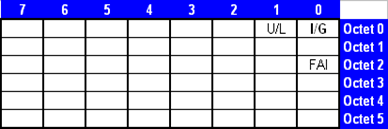
So, like our friend Scott Morris likes to say, the least significant bit of the most significant byte is the I/G bit! And looking at our Multicast Address 01-00-5E (in binary 0000 0001-0000 0000-0101 1110)  we can see that this I/G bit is set to 1 in EVERY Multicast!

In that case, the I/G bit defines a Multicast when it´s set to 1, but, how about the Broadcasts?! All bits in a Layer 2 Broadcast are set to 1 (including the I/G bit), so, Layer 2 Broadcasts, in fact, ARE a subset of Layer 2 Multicasts.

All Layer 2 Broadcasts are Multicasts.

All Layer 2 Multicasts are not Broadcasts.

With that in mind, when configuring Storm-Control in a switch port, and, if you´re setting limits to both Multicast and Broadcast, you should set Multicast limit HIGHER than the Broadcast limit (at least set they equal, but never set the Multicast level to be less than the Broadcast level, otherwise, either Broadcasts and Multicasts will be limited by the Multicast level, making pointless the Storm-Control configuration for the Broadcast!).

It´s configured on a per-interface basis, here´s the command list:

(config-if)#storm-control broadcast level (#)[.(#)]
(config-if)#storm-control multicast  level (#)[.(#)]
(config-if)#storm-control unicast level (#)[.(#)]


Level is % of line as maximum threshold
Level 100 would permit everything
Level 0.0 would disable the frame type

The following example will enable Unicast Storm-Control on a switch port with an 89% rising suppression level and a 67% falling suppression (remember, falling suppression can only be configured in 3560). It´ll also enable Broadcast Storm-Control on a port to a level of 20%. When the Broadcast exceeds the configured level of 20% of the total available bandwidth of the port within the traffic-storm-control interval, the switch drops all broadcast traffic until the end of the traffic-storm-control interval:

interface gigabitethernet0/1
storm-control unicast level 89 67
storm-control broadcast level 20

Just remember, Multicast levels (which includes more things) must be higher, or at least equal, to the Broadcast levels when configuring Storm-Control!

You can use the show storm-control command to verify the operation!

Nice! :)

More information available in do following Websites:

http://tcpmag.com/qanda/article.asp?EditorialsID=317

http://www.synapse.de/ban/HTML/P_LAYER2/Eng/P_lay207.html

http://www.faqs.org/rfcs/rfc1469.html

http://www.cisco.com/en/US/docs/switches/lan/catalyst3560/software/release/12.2_46_se/configuration/guide/swtrafc.html

Saturday, August 23, 2008

VACL, VLAN Maps & MAC ACL

A while back, more specific in July/14 we talked briefly about VACLs. That was when I took the IPExpert Volume 1 - Section 2: Quad Catalyst (PVST+) Switch Configuration. It´s not a very difficult task to be achieved, but TRICKY!

A friend from India (yeah Vipul, it´s you buddy!) asked me some things about it. So I´ll just elaborate it a while more. Also, at IPExpert CCIE R&S BLS you´ll find more info regarding that in the Security Section. It´s really well explained there! I would take sometime and review it with attention. The first time I watched it, I was like moving back and forward all the time to take notes, and to really stick the info in my head!

So,  starting with the basics... In a L2/L3 switch (like the ones in the CCIE Lab), where we can implement security?! Well, we can do it at the:

  1. Port Level - We can implement an Access-List in a particular port, and that will affect the traffic coming and going out of it (normally, it´ll affect only one host traffic). But imagine to implement that solution in many ports, over several equipment. Not very nice, right?!
  2. SVI - We can also implement an Access-List at the SVI Port! It´ll work everytime your switch is routing traffic between this particular VLAN and some other! Essentially, it´ll filter the traffic passing through the SVI.

Ok! So... Port-Level filters only that particular port.... SVI the routed traffic... and how about the INTRA-VLAN Traffic?! None of them will filter that!

VLAN Access-Lists (or VACL) works exactly there! At the Intra-VLAN Traffic! So everytime you need to filter internal traffic for a particular VLAN, VACL is your choice!

Just a couple more things to have in mind before getting into an example.

  1. IP Packets can only be processed by IP Access-Lists;
  2. Non-IP Packets like ARP, MAC-Addresses, and others can only be processed by MAC Access-Lists.

The MAC Access-Lists will bring all the interesting issues to the table... just check it out!

Let´s suppose for example you have two computers one with MAC Address 000b.dc24.ca47 and the second with the MAC Address 000b.dc25.cb51, both connected to VLAN7, and you want to allow all "non-IP" frames sourced from those two MAC Addresses to be forward anywhere, and also allowing only ICMP for example, denying everything else!

So, we have two different requirements there...

  1. Forward all "non-IP" frames sourced from those two specific MAC Addresses; That requires a MAC Access-List.
  2. Permit only ICMP, denying everyting else. That requires an IP Access-List (the one we´re all used to).

Ok, so let´s create our MAC Access-List:

mac access-list extended AllowThose
permit 000b.dc24.ca47 any
permit 000b.dc25.cb51 any

That will handle the first requirement.

Now the second one IP Access-List allowing ICMP and denying everything else:

access-list 101 permit icmp any any

Ok! Now, we need to create the VACL (or VLAN Maps, which one you preffer to call it) applying those rules:

vlan access-map Filter-VL7 10
action forward
match mac address AllowThose
!
vlan access-map Filter-VL7 20
action forward
match ip address 101
!
vlan access-map Filter-VL7 30
action drop

Now it looks ok, right?! Time to apply it to VLAN7 ?! What do you think about?! Let´s try?!

vlan filter Filter-VL7 vlan-list 7

Now testing! See if you can ping! Not working?! Hmmm... interesting... but why?! Well... I told... The MAC Access-List would bring all the interesting issues to the table! And, in fact,  it did! It´s allowing only those two MAC Address and nothing else! How about ARP?! Do we need it to make things work?! Of course we do! And that´s where we have most confusion! Just keep in mind, the end of an Access-List is always deny any any! So if there are no matching instances for ARP in the MAC Access-List, it´ll be dropped!

How to fix it?! Simple, allow it in the MAC Access-List:

permit any any 0x0806 0x0000
permit any any lsap 0xAAAA 0x0000

But wait a minute! What´s that 0x0806 and lsap 0xAAAA ?! That´s the Ethertypes we´re allowing in our MAC Access-List, first one (0x806) is ARP, and the second one (lsap 0xAAAA) is PVST+. You do not want your switch running unprotected from loops right?! So it´s better to allow it!

For the sake of simplicity, the full configuration would be this one:

mac access-list extended AllowThose
permit 000b.dc24.ca47 any
permit 000b.dc25.cb51 any
permit any any 0x0806 0x0000
permit any any lsap 0xAAAA 0x0000
!
access-list 101 permit icmp any any
!
vlan access-map Filter-VL7 10
action forward
match mac address AllowThose
!
vlan access-map Filter-VL7 20
action forward
match ip address 101
!
vlan access-map Filter-VL7 30
action drop
!
vlan filter Filter-VL7 vlan-list 7

The most common Ethertypes are: (and probably the ones asked in the LAB)

  • 0x0806 = ARP
  • lsap 0xAAAA = PVST+
  • 0x4242 = STP and PVST
  • 0x86DD = IPv6

Again... we need to understand all the little pieces involved in a particular task, and remember about the basics, OSI Model, ARP, and so on! It´s not difficult, but it´s a little confusing at the first time! Just go ahead, drink some watter (I did it several times) come back again, read over, and try some scenarios yourself, don´t have equipment?! Try it on Notepad, just try some, compare with the example, and you´ll see how easy it can be! The best way to learn is trying it yourself! ;)

You can also find a nice explanation about that in the wonderful Arden  Packeer´s Blog, just click here and it´ll direct you to the post.

Thursday, August 14, 2008

ARP, RARP, Proxy ARP, Gratuitous ARP and IP Redirect

Well... after a while away from my computer (in fact, away from any computer) due to some medical issues I´m back! Don´t worry, nothing bad, it was scheduled already, and I had the company of my wife, and guess who?! Yeah! Him! Mr. Jeff Doyle, not in person, but in his book version!

Books like TCP/IP Vol. 1 and 2 MUST be read from cover to cover! Always a good thing to learn!

Some of you may think, ARP, too basic... Yeah, I think too, but there were more than 10, 20 times that people who were supposed to know this asked me HOW it works... so here (with mr. Doyle´s help) you´ll find ARP some variations of  it.

ARP

Address Resolution Protocol (ARP) is used to map a known IP Address to a unkown data-link identifier (for example MAC Address). The ARP Request will contain:

  • Source IPv4 Address;
  • Source data-link identifier address (MAC Address for example);
  • Destination IPv4 Address;
  • Destination data-link identifier (MAC Address in our example) will be set to 00:00:00:00:00:00.

Check this ARP Request capture:

Ethernet II, Src: 00:30:b8:83:cb:40, Dst: ff:ff:ff:ff:ff:ff
    Destination: ff:ff:ff:ff:ff:ff (Broadcast)
    Source:
00:30:b8:83:cb:40  (00:30:b8:83:cb:40 )
    Type: ARP (0x0806)
    Trailer: FFE000200020003035800000FFE000100030               Address Resolution Protocol (request)
    Hardware type: Ethernet (0x0001)
    Protocol type: IP (0x0800)
    Hardware size: 6
    Protocol size: 4
    Opcode: request (0x0001)
    Sender MAC address:
00:30:b8:83:cb:40 (00:30:b8:83:cb:40)
    Sender IP address: 201.6.115.1 (201.6.115.1)
    Target MAC address: 00:00:00_00:00:00 (00:00:00:00:00:00)
    Target IP address: 201.6.115.254 (201.6.115.254)

By default Cisco Routers holds the ARP entries for 4 hours. You can change this value per interface basis with the command: arp timeout <value in seconds>. Example:

interface fastethernet 0/0
arp timeout 3600

RARP

RARP is the opposite of ARP, it maps an IPv4 Address to a know MAC Address, for example, old workstations  (dumb terminals) could have it´s firmware programmed to send a RARP request as soon as it was powered up, and a RARP Server would answer this RARP request with the workstation´s IP Address (Airline Companies used it ALOT in the past). Hmmm.. looks like DHCP right?! Yeah.. it looks, but it ISN´T ok?! ;)

RARP Request will contain:

  • Source and Destination data-link identifier (MAC Address in this example) will be the local host MAC Address;
  • Source and Destination IP Address will be set to 0.0.0.0.

Check this example capture of a RARP Traffic:

Ethernet II, Src: Marquett_12:dd:88, Dst: ff:ff:ff:ff:ff:ff
    Destination: ff:ff:ff:ff:ff:ff (Broadcast)
    Source:
Marquett_12:dd:88  (00:00:a1:12:dd:88)
    Type: ARP (0x0806)
    Trailer: FFE000200020003035800000FFE000100030               Address Resolution Protocol (reverse request)
    Hardware type: Ethernet (0x0001)
    Protocol type: IP (0x0800)
    Hardware size: 6
    Protocol size: 4
    Opcode: reverse request (0x0003)
    Sender MAC address:
Marquett_12:dd:88  (00:00:a1:12:dd:88) 
    Sender IP address: 0.0.0.0 (0.0.0.0)
    Target MAC address:
Marquett_12:dd:88  (00:00:a1:12:dd:88) 
    Target IP address:
0.0.0.0 (0.0.0.0)


---> EXAMPLE TOOK FROM Wireshark Wiki <---

Proxy ARP

A Proxy ARP enabled Router answers ARP requests intended for another machine, it does that by making the local host believe that the Router is the "owner" of that IP Address, local host will forward the traffic to the Router and the Router will be responsible to "route" the packets to the real destination.

For example, a Host in Subnet A wants to send traffic to Host in Subnet B, Host A and Host B are in the same subnet, but in different broadcast domains. Host A will send an ARP Request with Host B IP Address, the Router connected to both subnets will answer to Host A request using it´s own MAC Address instead of Host B MAC Address.

Now when Host A wants to transmit traffic to Host B, it´ll send to the Router MAC Address and the Router will just forward the traffic to Host B. That´s why "Proxy ARP".

It´s used on networks where the hosts are not configured with a default-gateway.

Oh yeah... it´s enabled by default in the Cisco IOS, and you can disable it on a per-interface basis with the command: no ip proxy- arp

Gratuitous ARP

In some circunstances a Host (Router, Switch, Computer, etc) might send an ARP Request with it´s own address  as the target address... But, to his own address?! Why a host would do that!?

Well... there are some reasons... for example:

  • It´s use to update other devices ARP Table (when a device receives an ARP Request with an IP that it´s already in it´s cache, the cache will be updated with the new information;
  • HSRP Routers that takes over the control will send Gratuitous ARP out the network to update the cache table of other devices ;
  • To check for duplicate addresses (if the host receives a response, it´ll know that somebody is using the same IP Address).

You can check this Gratuitous ARP traffic captured with Wireshark (the best opensource sniffer out there):

Ethernet II, Src: 02:02:02:02:02:02, Dst: ff:ff:ff:ff:ff:ff
    Destination: ff:ff:ff:ff:ff:ff (Broadcast)
    Source: 02:02:02:02:02:02 (02:02:02:02:02:02)
    Type: ARP (0x0806)
    Trailer: 000000000000000000000000000000000000
Address Resolution Protocol (request/gratuitous ARP)
    Hardware type: Ethernet (0x0001)
    Protocol type: IP (0x0800)
    Hardware size: 6
    Protocol size: 4
    Opcode: request (0x0001)
    Sender MAC address: 02:02:02:02:02:02 (02:02:02:02:02:02)
    Sender IP address: 192.168.1.1 (192.168.1.1)
    Target MAC address: ff:ff:ff:ff:ff:ff (Broadcast)
    Target IP address: 192.168.1.1 (192.168.1.1)


---> EXAMPLE TOOK FROM Wireshark Wiki <---

IP Redirect: 

IP Redirect is used by routers to notify hosts of another router on the data link that should be used for a particular destination.

For example, Router A and Router B are connected to the same Ethernet Segment, so as Host C. Host C has Router A set as default-gateway, Host C will send the packets to Router A, and Router A sees that the destination address of the packet is reachable via Router B, so Router A must forward the packets out the same interface it has received to Router B. Router A does that, and also, sends an ICMP Redirect to Host C informing to use Router B to reach this particular destination next time.

IP Redirect is enable by default in IOS Routers and can be disabled on a per interface basis with the command: no ip redirects.

That´s it! I´ll lie down a while, my head is a little fuzzy right now!

Monday, August 4, 2008

L2-Tunnels

This weekend was a bit more productive than last one! I was able to finish Day 1 of IPExpert CCIE R&S Blended Learning Solutions, plus, I got time to do some reading through Doyle´s TCP/IP Book! That was cool! I just need to keep my notes all together, and made that "understandable" to blog it!

Let´s start with L2-Tunnels, I still having some Switching notes I want to blog about, but, I´ll work a little more on them before it! In the mean time, L2-Tunneling, that was kind of "unknown" topic for me, seens quite simple now, as usual, there are some tricks to be aware about (like looping in our topology) and everything else like that!

L2Tunnel

Let say you want (or even better, your lab task want) you to have R1 and R2 showing each other as neighbors in CDP, without any action, using our topology above, if I type show cdp neighbors in R1, it´ll show me SW1 as a neighbor, same goes to R2, that will show SW2 as neighbor...

So, how to accomplish?! Using L2-Tunnels. L2-Tunnels are used to get the  switches in the middle (in our case SW1 and SW2) to tunnel L2 information and passes it to the other device (R1 and R2), even if we know the normal behavior of a switch is to process CDP, PaGP, STP packets locally, they´ll tunnel it (according to what we actually configure in the switch), and just forward to the other end.

Keep in mind that switch ports cannot be in "dynamic" mode, they must be in "access" or "dot1q-tunnel". Otherwise our L2-Tunnel will not work.

Configuration to complete this task is really straight-forward (those commands apply to both switches SW1 and SW2 edge ports - connected to the routers R1 and R2 in this case):

int f0/5
switchport mode access
switchport access vlan 12
no cdp enable
L2protocol-tunnel cdp

Now, VLAN 12 is "trunked" through switches! All switches in the middle are just "L2 Trunks" that will carry information normally from one side to another.

Another thing to keep in mind is: Multicast (and broadcasts) are flooded to all available ports, so make sure VLAN 12 (in our case) used for carrying L2 Tunnel does not come back to original end switches, because Loopguard will disable ports if so. Use switchport trunk allowed to filter it. This is very important!!!!

If, you want that R1 shows SW1 and R2 as CDP Neighbors, just enable CDP in the switch fastethernet port (cdp enable), and that´s it!

Tuesday, July 22, 2008

Integrated Routing and Bridging Example

Here follows an example of IRB, that will probably make our understanding about this topic a bit easier. This scenario  was based in the Video on Demand from IPExpert CCIE R&S Blended Learning Solutions. A full video dedicated just to it is available in there, and I recommend you to check it out! It rocks! :)

Take a look at the topology:

Bridging

Those VLANs (VLAN2 and VLAN3) will be bridged through our serial link.

In order to do that, we need to:

  1. Create the Bridge-Group;
  2. Assign this Bridge-Group to our Interfaces;
  3. Create the BVI Interface and assigns an IP Address to it;
  4. Create our rules (specifically tell this particular Bridge- Group to Route IP) .

First... what is the function of a "Bridge-Group" ?! Well "Bridge-Group" job is to take  packets to an unknow destination and flood them out any available ports, or more important, to learn were those available ports are for each them.

The catch is, the router can do routing,  can do bridging, but in other to do both, like some interfaces to route, some interfaces to bridge we need to use IRB (Integrated Routing and Bridging).

Take a look in the configuration for all devices involved, interfaces FastEthernet0/0 and Serial1/1 in our routers R2 and R3 were assigned to Bridge-Group 1, all interfaces between the origin and destination will be "bridged", the IP Address will be assigned to the BVI Interface, take a look:

R2:

int f0/0
bridge-group 1
no shut
!
int s1/1
 bridge-group 1
no shut
!
bridge irb
bridge 1 protocol ieee
bridge 1 route ip

!
int bvi 1
ip address 111.111.111.2 255.255.255.0
no shut

R3:

int f0/0
bridge-group 1
no shut
!
int s1/1
bridge-group 1
no shut
!
bridge irb
bridge 1 protocol ieee
bridge 1 route ip

!
int bvi 1
ip address 111.111.111.3 255.255.255.0
no shut

SW2

int f1/2
switchport access vlan 2
no shut
!
int vlan 2
ip address 111.111.111.22 255.255.255.0
no shut
exit

SW3

int f1/3
switchport access vlan 3
no shut
!
int vlan 3
ip address 111.111.111.33 255.255.255.0
no shut
exit

To make double-sure about our IP assignment, we can use the show ip int brief command:

R2#sh ip int brief
Interface       IP-Address    OK? Method Status      Protocol
FastEthernet0/0 unassigned    YES unset  up          up
Serial1/0       unassigned    YES unset administrat. down down
Serial1/1       unassigned    YES manual up          up
BVI1            111.111.111.2 YES manual up          up

R3#sh ip int brief
Interface       IP-Address    OK? Method Status      Protocol
FastEthernet0/0 unassigned    YES unset  up          up
Serial1/0       unassigned    YES unset  administrat. down down
Serial1/1       unassigned    YES manual up          up
BVI1            111.111.111.3 YES manual up          up

Everything looks good, BVI interface has it´s IP Addresses, and both FastEthernet and Serial interfaces don´t!

Using the command show bridge 1 verbose we can check which interfaces belongs to this specific Bridge-Group:

R2#sh bridge 1 verbose

Flood ports (BG 1)           RX count    TX count
FastEthernet0/0                     0           0
Serial1/1                           0           0

Seens fine too! So, what next?! Testing! How?! Ping!!!

R2#ping 111.111.111.22

Type escape sequence to abort.
Sending 5, 100-byte ICMP Echos to 111.111.111.22, timeout is 2 seconds:
!!!!!
Success rate is 100 percent (5/5), round-trip min/avg/max = 28/68/128 ms


R2#ping 111.111.111.3

Type escape sequence to abort.
Sending 5, 100-byte ICMP Echos to 111.111.111.3, timeout is 2 seconds:
!!!!!
Success rate is 100 percent (5/5), round-trip min/avg/max = 28/58/136 ms


R2#ping 111.111.111.33

Type escape sequence to abort.
Sending 5, 100-byte ICMP Echos to 111.111.111.33, timeout is 2 seconds:
!!!!!
Success rate is 100 percent (5/5), round-trip min/avg/max = 60/83/140 ms

---------------

R3#ping 111.111.111.2

Type escape sequence to abort.
Sending 5, 100-byte ICMP Echos to 111.111.111.2, timeout is 2 seconds:
!!!!!
Success rate is 100 percent (5/5), round-trip min/avg/max = 32/65/128 ms


R3#ping 111.111.111.22

Type escape sequence to abort.
Sending 5, 100-byte ICMP Echos to 111.111.111.22, timeout is 2 seconds:
!!!!!
Success rate is 100 percent (5/5), round-trip min/avg/max = 44/88/144 ms


R3#ping 111.111.111.33

Type escape sequence to abort.
Sending 5, 100-byte ICMP Echos to 111.111.111.33, timeout is 2 seconds:
!!!!!
Success rate is 100 percent (5/5), round-trip min/avg/max = 32/58/120 ms

---------------

SW2#ping 111.111.111.2

Type escape sequence to abort.
Sending 5, 100-byte ICMP Echos to 111.111.111.2, timeout is 2 seconds:
!!!!!
Success rate is 100 percent (5/5), round-trip min/avg/max = 32/64/136 ms


SW2#ping 111.111.111.3

Type escape sequence to abort.
Sending 5, 100-byte ICMP Echos to 111.111.111.3, timeout is 2 seconds:
!!!!!
Success rate is 100 percent (5/5), round-trip min/avg/max = 56/95/184 ms


SW2#ping 111.111.111.33

Type escape sequence to abort.
Sending 5, 100-byte ICMP Echos to 111.111.111.33, timeout is 2 seconds:
!!!!!
Success rate is 100 percent (5/5), round-trip min/avg/max = 80/127/200 ms

---------------

SW3#ping 111.111.111.3

Type escape sequence to abort.
Sending 5, 100-byte ICMP Echos to 111.111.111.3, timeout is 2 seconds:
!!!!!
Success rate is 100 percent (5/5), round-trip min/avg/max = 32/72/124 ms

SW3#ping 111.111.111.2

Type escape sequence to abort.
Sending 5, 100-byte ICMP Echos to 111.111.111.2, timeout is 2 seconds:
!!!!!
Success rate is 100 percent (5/5), round-trip min/avg/max = 48/105/164 ms

SW3#ping 111.111.111.22

Type escape sequence to abort.
Sending 5, 100-byte ICMP Echos to 111.111.111.22, timeout is 2 seconds:
!!!!!
Success rate is 100 percent (5/5), round-trip min/avg/max = 92/145/224 ms


Now we have reachability between the two vlans! We can use the command show bridge 1 verbose again to check  the counters and the interfaces involved in this particular bridge group:

R2#sh bridge 1 verbose

Total of 300 station blocks, 297 free
Codes: P - permanent, S - self

BG Hash  Address     Action Interface  VC Age  RX count TX count
1 00/0   cc02.09c0.0000 forward  Serial1/1       -  3  10   9
1 00/1   cc05.0f10.0000 forward  Serial1/1       -  1  25  24
1 00/2   cc04.0f10.0000 forward  FastEthernet0/0 -  1  30  28

Flood ports (BG 1)           RX count    TX count
FastEthernet0/0                     7           0
Serial1/1                           0           7

R3#sh bridge 1 verbose

Total of 300 station blocks, 297 free
Codes: P - permanent, S - self

BG Hash  Address     Action Interface  VC Age  RX count TX count
1 00/0   cc04.0f10.0000 forward  Serial1/1       -  2  20   19
1 00/1   cc01.09c0.0000 forward  Serial1/1       -  0  15   14
1 00/2   cc05.0f10.0000 forward  FastEthernet0/0 -  0  35   33

Flood ports (BG 1)           RX count    TX count
FastEthernet0/0                     6           0
Serial1/1                           0           0

Just for curiosity, show arp at R3...

R3#sh arp
Protocol  Address     Age (min)  Hardware Addr   Type   Interface
Internet  111.111.111.33        5   cc05.0f10.0000  ARPA   BVI1
Internet  111.111.111.3         -   cc02.09c0.0000  ARPA   BVI1
Internet  111.111.111.2         5   cc01.09c0.0000  ARPA   BVI1
Internet  111.111.111.22        5   cc04.0f10.0000  ARPA   BVI1

...and show arp at SW2:

SW2#sh arp
Protocol  Address     Age (min)  Hardware Addr   Type   Interface
Internet  111.111.111.33        6   cc05.0f10.0000  ARPA   Vlan2
Internet  111.111.111.3         6   cc02.09c0.0000  ARPA   Vlan2
Internet  111.111.111.2         7   cc01.09c0.0000  ARPA   Vlan2
Internet  111.111.111.22        -   cc04.0f10.0000  ARPA   Vlan2

As you can see, everything is working fine! I do recommend you to check IPExpert Bridging Videos, and also Cisco DocCD for more information!

Follows some usefull links:

http://www.cisco.com/en/US/tech/tk389/tk815/technologies_tech_note09186a0080094663.shtml

http://www.cisco.com/en/US/docs/ios/bridging/configuration/guide/br_transprnt_brdg_ps6350_TSD_Products_Configuration_Guide_Chapter.html#wp1003018

Monday, July 21, 2008

Bridging & Integrated Routing and Bridging

Everything went wrong this last weekend, I was a bit sick with fever and all this kind of stuff, and spent more time in bed, than actually doing anything else... That delayed me a little, I had plans to complete Workbook Volume 1 labs 3 and 4 this weekend but that wasn´t possible!

Today I´m better, really better, and in my lunch time I reviewed IPExpert CCIE R&S BLS Bridging Video. Nice topic, this is something we don´t get to see every day! In fact... I´ve never saw anything actually "bridged" in a network, and even it´s not on blueprint anymore we can still having some IRB Bridging. So I´ll spent more time on that for sure!

Couple quick notes I was able to get from the Video:

Basic job of a bridge is to bring things together, transparent bridging does that using the same media type, same MTU size, nothing changes!

Bridging on Routers:

Setup the basic bridge function:

  • Bridge 1 protocol ieee

Then bind to interfaces:

  • Bridge-group 1

If Frame-Relay is in the middle:

  • Frame-relay  map bridge <DLCI>

Integrated Routing & Bridging:

Allows selective routing some protocols while bridging others:

Enable Bridge IRB in a router:

  • Bridge irb

Configure a BVI (Bridging Virtual Interface):

  • Interface bvi 1
    • ip address <address> <mask>

Create our "rules", in other words tell bridge-group 1 to route IP.

  • Bridge 1 route ip

Interfaces in middle simply have bridging.

A cool command to verify if everything is working (AFTER ping testing):

  • Show bridge 1 verbose

It seens a little confuse, but with the example showed in the Video on Demand you´re able to get it! I´ll try to create a Dynamips topology to simulate a bridging scenario and post back later, to clarify things a bit better either for you reading this, and for me! :)

Tuesday, July 15, 2008

PPP Video on Demand (IPExpert CCIE R&S BLS)

Today I was watching the PPP Video-on-Demand from IPExpert´s CCIE R&S Blended Learning Solutions, and learned some new tricks! AWESOME!

PPP is fair simple, configuring it is not that difficult, BUT, as always, there are a couple tricks we can be asked in the exam, and that´s exactly WHERE the Video-on-Demand comes to rescue!

The worse thing that they could ask in the exam about PPP is  Authentication! Otherwise, we just set the encapsulation to ppp bring our interfaces up and that´s pretty much it!

In the PPP Video we get the chance to review some scenarios, not difficult ones, but trick!

First, let´s take a look at the topology used in our simulation (again, I was running it in Dynamips, if anybody wants the .NET files, just let me know):

PPP

First scenario: R2 should initiate a secure authentication request to R3.

So, how to complete this task?!

Secure means the password cannot be sent in Clear-Text, so PAP is out, we can use CHAP! CHAP sends a MD5 hash, so it´s good!

But, how can we make sure R2 will initiate the authentication, and not R3?! Well... in fact it´s very simple (I didn´t knew about that so far), use the command ppp authentication chap only in R2. The ppp authentication command only specifies what you´re going to send out  as an authentication requirement not what you´re going to respond to, you always responding to stuff.

So, our configuration will look pretty much like this one:

R2:

username R3 password 0 cisco
!

interface Serial1/1
ip address 222.222.222.2 255.255.255.0
encapsulation ppp
clock rate 128000
ppp authentication chap

R3:

username R2 password 0 cisco
!
interface Serial1/1
ip address 222.222.222.3 255.255.255.0
encapsulation ppp

To BE SURE that R2 is initiating the request, we can run a debug ppp authentication in both routers and check the Outgoing (O) and Incoming (I) requests, take a look yourself:

R2(config-if)#do debug ppp authentication
PPP authentication debugging is on
R2(config-if)#
Se1/1 PPP: Using default call direction
Se1/1 PPP: Treating connection as a dedicated line
Se1/1 PPP: Session handle[400001F] Session id[63]
Se1/1 PPP: Authorization required
Se1/1 CHAP: O CHALLENGE id 1 len 23 from "R2"
Se1/1 CHAP: I RESPONSE id 1 len 23 from "R3"
Se1/1 PPP: Sent CHAP LOGIN Request
Se1/1 PPP: Received LOGIN Response PASS
Se1/1 PPP: Sent LCP AUTHOR Request
Se1/1 PPP: Sent IPCP AUTHOR Request
R2(config-if)#
Se1/1 LCP: Received AAA AUTHOR Response PASS
Se1/1 IPCP: Received AAA AUTHOR Response PASS
Se1/1 CHAP: O SUCCESS id 1 len 4
Se1/1 PPP: Sent CDPCP AUTHOR Request
Se1/1 CDPCP: Received AAA AUTHOR Response PASS
Se1/1 PPP: Sent IPCP AUTHOR Request
R2(config-if)#
%LINEPROTO-5-UPDOWN: Line protocol on Interface Serial1/1, changed state to up

R3(config-if)#do debug ppp authentication
PPP authentication debugging is on
R3(config-if)#

Se1/1 CHAP: I CHALLENGE id 1 len 23 from "R2"
Se1/1 CHAP: Using hostname from unknown source
Se1/1 CHAP: Using password from AAA
Se1/1 CHAP: O RESPONSE id 1 len 23 from "R3"
Se1/1 CHAP: I SUCCESS id 1 len 4
R3(config-if)#
%LINEPROTO-5-UPDOWN: Line protocol on Interface Serial1/1, changed state to up

So what´s next?! Just try to ping from both sides, and you should be ok at your exam! Nothing more to worry about!

Second scenario: R2 and R3 should be configured to PPP Authentication using DIFFERENT secure authentication protocols.

Hmmm... is that possible?! Yeah, it is! We´ll be using CHAP in R2, and EAP in R3, and everything will be good!

Check the configuration of both routers:

R2:

username R3 password 0 cisco
!
interface Serial1/1
ip address 222.222.222.2 255.255.255.0
encapsulation ppp
clock rate 128000
ppp authentication chap
 ppp eap password 0 cisco


R3:

username R2 password 0 cisco
!

interface Serial1/1
ip address 222.222.222.3 255.255.255.0
encapsulation ppp
ppp authentication eap
ppp eap local

Seens pretty straight-forward! Just a quick overview of this configuration:

In R2 the command ppp eap password  cisco needs to be used, because the password in EAP doesn´t need to be symmetric, so we MUST configure it in the CHAP side of the link.

Regarding the ppp eap local configured in R3, this command means, use the LOCAL database (that means username R2 password cisco) for authentication, instead of a Radius Server. If you do not use this command, EAP will expect to have a Radius Server to authenticate the connection, and we do not have it!

Doing that, R2 and R3 will be configured with two different secure authentication protocols! We´re good! That´s what we were asked for!

Take a look at this Debug Output:

R2(config-if)#do debug ppp authentication
PPP authentication debugging is on
R2(config-if)#
%LINK-3-UPDOWN: Interface Serial1/1, changed state to up
Se1/1 CHAP: O CHALLENGE id 60 len 23 from "R2"
Se1/1 EAP: I REQUEST  IDENTITY id 71 len 5
Se1/1 EAP: O RESPONSE IDENTITY id 71 len 7 from "R2"
Se1/1 EAP: I REQUEST  MD5 id 72 len 24 from "R3"
Se1/1 CHAP: I RESPONSE id 60 len 23 from "R3"

Se1/1 PPP: Sent CHAP LOGIN Request
Se1/1 EAP: Using hostname from unknown source
Se1/1 EAP: Using password from interface EAP
Se1/1 EAP: O RESPONSE MD5 id 72 len 24 from "R2"
Se1/1 PPP: Received LOGIN Response PASS
Se1/1 PPP: Sent LCP AUTHOR Request
Se1/1 PPP: Sent IPCP AUTHOR Request
Se1/1 EAP: I SUCCESS id 72 len 4
Se1/1 LCP: Received AAA AUTHOR Response PASS
Se1/1 IPCP: Received AAA AUTHOR Response PASS
Se1/1 CHAP: O SUCCESS id 60 len 4
Se1/1 PPP: Sent CDPCP AUTHOR Request
Se1/1 CDPCP: Received AAA AUTHOR Response PASS
Se1/1 PPP: Sent IPCP AUTHOR Request
R2(config-if)#
%LINEPROTO-5-UPDOWN: Line protocol on Interface Serial1/1, changed state to up

R3(config-if)#do debug ppp authentication
PPP authentication debugging is on
R3(config-if)#
%LINK-3-UPDOWN: Interface Serial1/1, changed state to up
Se1/1 EAP: O REQUEST  IDENTITY id 73 len 5
Se1/1 CHAP: I CHALLENGE id 61 len 23 from "R2"
Se1/1 CHAP: Using hostname from unknown source
Se1/1 CHAP: Using password from AAA
Se1/1 CHAP: O RESPONSE id 61 len 23 from "R3"
Se1/1 EAP: I RESPONSE IDENTITY id 73 len 7 from "R2"
Se1/1 EAP: O REQUEST  MD5 id 74 len 24 from "R3"
Se1/1 CHAP: I SUCCESS id 61 len 4
Se1/1 EAP: I RESPONSE MD5 id 74 len 24 from "R2"

Se1/1 PPP: Sent CHAP LOGIN Request
Se1/1 PPP: Received LOGIN Response PASS
Se1/1 PPP: Sent LCP AUTHOR Request
Se1/1 PPP: Sent IPCP AUTHOR Request
Se1/1 LCP: Received AAA AUTHOR Response PASS
Se1/1 IPCP: Received AAA AUTHOR Response PASS
Se1/1 EAP: O SUCCESS id 74 len 4
Se1/1 PPP: Sent CDPCP AUTHOR Request
Se1/1 CDPCP: Received AAA AUTHOR Response PASS
Se1/1 PPP: Sent IPCP AUTHOR Request
%LINEPROTO-5-UPDOWN: Line protocol on Interface Serial1/1, changed state to up

Again, a ping test will not hurt (it worked for me in my Dynamips simulation).

Those are the kind of situations we may encounter during the exam, and for sure, after watching this PPP Video that will not cause me any problems! Cool! :)

There are a lot more tips and advices like that in the Video (not only for PPP, but for everything), you have to check it out! :D

Friday, July 11, 2008

PPP over Frame-Relay Example

Until few days ago, PPP over Frame-Relay was a bit confusing to me, not that I knew it or not, but I´d never configured it so far, just saw it on theory...

This week, after checking the VoD from IPExpert, things became much easier!

To clear things out, PPP over Frame-Relay is used to bundle PVCs together (or also for authentication over Frame-Relay links).

Frame-Relay multilink is used to bundle LINKs together.

So, in this example, we´ll be checking the PPP over Frame-Relay option,  take a look at the topology used:

PPPoFR

Ok! First things first, the drawing is not showing  the PVCs that we´re supposed to be using, so... how can we check this information?! Well... in fact it´s pretty easy... We can just configure the Serial Link with Frame-Relay encapsulation and check the PVCs (sh frame-relay pvc) configured in our Frame-Relay Switch (not in the diagram):

R1, R2, R3

int s1/0
encap frame-relay
no frame inverse-arp
no shut

After the sh frame-relay pvc command, we can see that we have a FULL-MESH network, but, we´re not going to use them all!

According to the drawing, we need two PVCs between R1 and R3 (103, 113 and 301, 311), as far as the task is not asking for anything specific, we can use any PVC that we want to achieve the goal. Also, we need only one PVC between R1 and R2 (102 and 201). How about the others?! Well... leave them for now, they´re not going to be used in this task!

R1(config-if)#do sh frame pvc | in ACT
DLCI = 102, DLCI USAGE = UNUSED, PVC STATUS = ACTIVE, INTERFACE = Serial1/0
DLCI = 103, DLCI USAGE = UNUSED, PVC STATUS = ACTIVE, INTERFACE = Serial1/0
DLCI = 112, DLCI USAGE = UNUSED, PVC STATUS = ACTIVE, INTERFACE = Serial1/0
DLCI = 113, DLCI USAGE = UNUSED, PVC STATUS = ACTIVE, INTERFACE = Serial1/0

R2(config-if)#do sh frame pvc | in ACT
DLCI = 201, DLCI USAGE = UNUSED, PVC STATUS = ACTIVE, INTERFACE = Serial1/0
DLCI = 203, DLCI USAGE = UNUSED, PVC STATUS = ACTIVE, INTERFACE = Serial1/0
DLCI = 211, DLCI USAGE = UNUSED, PVC STATUS = ACTIVE, INTERFACE = Serial1/0

R3(config-if)#do sh frame pvc | in ACT
DLCI = 301, DLCI USAGE = UNUSED, PVC STATUS = ACTIVE, INTERFACE = Serial1/0
DLCI = 302, DLCI USAGE = UNUSED, PVC STATUS = ACTIVE, INTERFACE = Serial1/0
DLCI = 311, DLCI USAGE = UNUSED, PVC STATUS = ACTIVE, INTERFACE = Serial1/0

Now... in order to configure PPP over Frame-Relay, we need to create a virtual-template interface, and point the DLCIs that we´re going to be  using to this virtual-template interface that we just created, take a look on how all three routers were configured  (in this specific case, R1 and R3 are the only ones using PPP over Frame-Relay):

R1

int virtual-template 1
ip address 200.200.230.1 255.255.255.0
bandwitdh 64
no shut
!
int s1/0
frame interface-dlci 103 ppp virtual-temp 1
frame interface-dlci 113 ppp virtual-temp 1
!
int s1/0.102 point-to-point
ip address 200.200.220.1 255.255.255.0
frame-relay interface-dlci 102 broadcast

R2

int s1/0.201 point-to-point
bandwitdh 64
ip address 200.200.220.2 255.255.255.0
frame-relay interface-dlci 201 broadcast

R3

int virtual-template 1
bandwitdh 64
ip address 200.200.230.3 255.255.255.0
no shut
!
int s1/0
frame interface-dlci 301 ppp virtual-temp 1
frame interface-dlci 311 ppp virtual-temp 1

So, time for a quick test?! Yeah! It is! Let´s try to ping R2 and R3 from R1:

R1(config-fr-dlci)#do ping 200.200.220.2

Type escape sequence to abort.
Sending 5, 100-byte ICMP Echos to 200.200.220.2, timeout is 2 seconds:
!!!!!
Success rate is 100 percent (5/5), round-trip min/avg/max= 20/60/112 ms

R1(config-fr-dlci)#do ping 200.200.230.3

Type escape sequence to abort.
Sending 5, 100-byte ICMP Echos to 200.200.230.3, timeout is 2 seconds:
!!!!!
Success rate is 100 percent (5/5), round-trip min/avg/max = 20/70/120 ms

It worked! Things seens good, don´t you think?! If we check the interfaces at R1 (show ip int brief), we can see our Virtual-Template1 interface down and what in the world are those Virtual-Access interfaces?! We never configured those!

In fact, the Virtual-Template will remain down, and each time the PPP connection gets reseted (up, down, up again, shut, or anything else) a new Virtual-Access interface (one for each DLCI)  will be created and those are the interfaces that will remain up/up for our connection. So the Virtual-Access interfaces are created everytime the PPP connection gets up!

R1(config-if)#do sh ip int brief
Interface         IP-Address     OK? Method Status     Protocol
FastEthernet0/0   unassigned     YES unset  down       down Serial1/0         unassigned     YES unset  up         up
Serial1/0.102     200.200.220.1  YES manual up         up
Virtual-Template1 200.200.230.1  YES manual down       down
Virtual-Access2   200.200.230.1  YES TFTP   up         up
Virtual-Access3   200.200.230.1  YES TFTP   up         up

A good thing to do also is to check the Routing Table...

R1(config-fr-dlci)#do sh ip route
Codes: C - connected, S - static, R - RIP, M - mobile, B - BGP
D - EIGRP, EX - EIGRP external, O - OSPF, IA - OSPF inter area
N1 - OSPF NSSA external type 1, N2 - OSPF NSSA external type 2
E1 - OSPF external type 1, E2 - OSPF external type 2
i - IS-IS,su -IS-IS summary,L1-IS-IS level-1,L2-IS-IS level-2
ia-IS-IS inter area,*-candidate default U-per-user static route
o - ODR, P - periodic downloaded static route

Gateway of last resort is not set

C    200.200.220.0/24 is directly connected, Serial1/0.102
     200.200.230.0/24 is variably subnetted, 2 subnets, 2 masks
C       200.200.230.3/32 is directly connected, Virtual-Access2
                         is directly connected, Virtual-Access3

C       200.200.230.0/24 is directly connected, Virtual-Access2
                         is directly connected, Virtual-Access3

The /32 entry was created by the PPP, and both Virtual-Access2 and Virtual-Access3 interfaces are there also, so what does the routing protocols will do?! They will load balance, and that´s not what we want in first place!

To solve it, we just go into the Virtual-Template interface and "multilink" them together, using the command ppp multilink, this will create another Virtual-Access interface that will bundle to two others!

R1, R3

int virtual-temp 1
ppp multilink

To check if the interfaces are bundled together, we can use the following show command: show ppp multilink.

R1#sh ppp multilink

Virtual-Access4, bundle name is R3
  Endpoint discriminator is R3
  Bundle up for 00:01:45, total bandwidth 128, load 1/255
  Receive buffer limit 24384 bytes, frag timeout 1524 ms
    0/0 fragments/bytes in reassembly list
    0 lost fragments, 0 reordered
    0/0 discarded fragments/bytes, 0 lost received
    0x2 received sequence, 0x2 sent sequence
  Member links: 2 (max not set, min not set)
    Vi2, since 00:01:46
    Vi3, since 00:01:46
No inactive multilink interfaces

R3(config-if)#do sh ppp multilink

Virtual-Access4, bundle name is R1
  Endpoint discriminator is R1
  Bundle up for 00:01:02, total bandwidth 128, load 1/255
  Receive buffer limit 24384 bytes, frag timeout 1524 ms
    0/0 fragments/bytes in reassembly list
    0 lost fragments, 0 reordered
    0/0 discarded fragments/bytes, 0 lost received
    0x2 received sequence, 0x2 sent sequence
  Member links: 2 (max not set, min not set)
    Vi2, since 00:01:03
    Vi3, since 00:01:03
No inactive multilink interfaces

And finally, we can check our routing table, and we see just the newly created Virtual-Access interface over there! Much better for our Routing Protocols!

R1(config-fr-dlci)#do sh ip route
Codes: C - connected, S - static, R - RIP, M - mobile, B - BGP
D - EIGRP, EX - EIGRP external, O - OSPF, IA - OSPF inter area
N1 - OSPF NSSA external type 1, N2 - OSPF NSSA external type 2
E1 - OSPF external type 1, E2 - OSPF external type 2
i - IS-IS,su -IS-IS summary,L1-IS-IS level-1,L2-IS-IS level-2
ia-IS-IS inter area,*-candidate default U-per-user static route
o - ODR, P - periodic downloaded static route

Gateway of last resort is not set

C    200.200.220.0/24 is directly connected, Serial1/0.102
     200.200.230.0/24 is variably subnetted, 2 subnets, 2 masks
C       200.200.230.3/32 is directly connected, Virtual-Access4
C       200.200.230.0/24 is directly connected, Virtual-Access4

These little notes about PPP over Frame-Relay were based on the Frame-Relay VoD from IPExpert CCIE R&S BLS, an extremelly helpfull resource for me so far!

Also, I´ve simulated this on Dynamips, so, if anyone wants the .NET file, just let me know, and I can forward it to your email!

Wednesday, July 9, 2008

Frame-Relay Video on Demand (BLS)

This afternoon I was entertaining  myself with the Frame-Relay Video-on-Demand from IPExpert´s CCIE R&S Blended Learning Solutions!

A LOT of cool stuff in there! I´ll try to simulate a few things on Dynamips tomorrow, if possible, to demonstrate it better!

Couple things I know for sure after watching those videosFrame-Relay Multilink and PPP over Frame-Relay are in fact very easy to configure. You just have to do it with attention and nothing will go wrong.

Another interesting one:

Frame-Relay Multilink: Used to bundle interfaces together.

PPP over Frame-Relay: Used to bundle PVCs together.

One more  thing that I didn´t knew (at least, I´ve never saw it that way)  about Frame-Relay: We can have Frame-Relay configurations in the  Physical Interface,  Point-to-Point,  Multipoint and PPP over Frame-Relay all in only one interface, no problems at all! You just have to configure the other side of the PVC accordingly and that´s it! We may have this type of scenario in the real lab!

Talking about the Lab, there are many good tips and advices about the exam itself, find here just a few:

If the lab is asking to configure several different PVCs, each with it´s own subnet, but it has a restriction to not use any kind of subinterface, that´s a good place to use PPP over Frame-Relay (virtual-templates).

Another one is if they´re asking for authentication in the PVCs, we´re supposed to use PPPoFR, it´s the only way to perform authentication in Frame-Relay PVCs.

And a LOT more! It´s definitely a MUST HAVE material for any serious CCIE Candidate!

I´m in a little rush right now, but I´ll try to simulate some scenarios tomorrow!

Take care!

Thursday, July 3, 2008

Frame-Relay LMI Basics

So... continuing with our Frame-Relay stuff, let´s take a look at our friend Local Management Interface (or LMI, as it preffers to be called). ;)

LMI is the protocol that exchanges information between your Router and the Frame-Relay Switch, it´ll carry information about DLCI status, Keepalives, etc. You can monitor the LMI traffic from your Router using the "debug frame-relay lmi" command.

Follows an output from a debug:

R1#debug frame-relay lmi
*Mar 1 00:15:13:Serial1/0(out):StEnq,myseq 52,yourseen 51,DTE up
*Mar 1 00:15:13: datagramstart = 0x7A01894, datagramsize = 14
*Mar 1 00:15:13: FR encap = 0x00010308
*Mar 1 00:15:13: 00 75 95 01 01 01 03 02 34 33
*Mar 1 00:15:13:
*Mar 1 00:15:13: Serial1/0(in): Status, myseq 52, pak size 14
*Mar 1 00:15:13: RT IE 1, length 1,
type 1
*Mar 1 00:15:13: KA IE 3, length 2, yourseq 52, myseq 52

...output omitted...

*Mar 1 00:16:43:Serial1/0(out):StEnq,myseq 61,yourseen 60,DTE up
*Mar 1 00:16:43: datagramstart = 0x7C08474, datagramsize = 14
*Mar 1 00:16:43: FR encap = 0x00010308
*Mar 1 00:16:43: 00 75 95 01 01 00 03 02 3D 3C
*Mar 1 00:16:43:
*Mar 1 00:16:43: Serial1/0(in): Status, myseq 61, pak size 24
*Mar 1 00:16:43: RT IE 1, length 1, type 0
*Mar 1 00:16:43: KA IE 3, length 2, yourseq 61, myseq 61
*Mar 1 00:16:43: PVC IE 0x7 ,length 0x3 , dlci 102, status 0x2
*Mar 1 00:16:43: PVC IE 0x7 ,length 0x3 , dlci 103, status 0x2

So, what can we understand about this output!? Hmmm... good question! Just checking it, we can identify that the first part is just a normal Keepalive, and the second one means a Full Status Update... Here is how we checked it:

Type 1 - is a Normal Keepalive (sent every 10 seconds by default)

Type 0 - is a Full Status Update, it is sent every 6th Keepalive, that means, if you don´t change the defaults, it´ll be sent every 60 seconds, and it´ll include the DLCI status, which can be:

-> 0x0 means "inactive"

-> 0x2 means "active" (the status we normally want!)

-> 0x3 means that the active DLCI cannot accept more traffic without drops ocurring - kind of a flow-control code

-> 0x4 means "deleted" 

So, checking the previous output we can see dlci 102, status 0x2, that means DLCI 102 is Active!

We can also check that using the "show frame-relay pvc" command:

R1#sh frame-relay pvc

PVC Statistics for interface Serial1/0 (Frame Relay DTE)

              Active      Inactive      Deleted       Static
  Local          2            0            0            0
  Switched       0            0            0            0
  Unused         0            0            0            0

DLCI=102, DLCI USAGE=LOCAL, PVC STATUS=ACTIVE,INTERFACE=Serial1/0

  input pkts 11            output pkts 7            in bytes 1074
  out bytes 588            dropped pkts 0       in pkts dropped 0
  out pkts dropped 0       out bytes dropped 0
  in FECN pkts 0           in BECN pkts 0         out FECN pkts 0
  out BECN pkts 0          in DE pkts 0             out DE pkts 0
  out bcast pkts 2         out bcast bytes 68
  5 minute input rate 0 bits/sec, 0 packets/sec
  5 minute output rate 0 bits/sec, 0 packets/sec
  pvc create time 00:07:21, last time pvc status changed 00:07:11

DLCI=103, DLCI USAGE=LOCAL, PVC STATUS=ACTIVE,INTERFACE=Serial1/0

  input pkts 1             output pkts 4            in bytes 34
  out bytes 136            dropped pkts 0       in pkts dropped 0
  out pkts dropped 0       out bytes dropped 0
  in FECN pkts 0           in BECN pkts 0         out FECN pkts 0
  out BECN pkts 0          in DE pkts 0             out DE pkts 0
  out bcast pkts 4         out bcast bytes 136
  5 minute input rate 0 bits/sec, 0 packets/sec
  5 minute output rate 0 bits/sec, 0 packets/sec
  pvc create time 00:07:22, last time pvc status changed 00:07:12

There are some good fields to be checked in this output, for example, the PVC STATUS and the DLCI USAGE.

The PVC Status can can have four possible states:

ACTIVE - PVC is up and functioning normally.

INACTIVE - PVC is not up end-to-end. This can be caused by several problems, like incorrect mapping (or no mapping at all) for the local DLCI in the frame-relay cloud, or the remote end of the PVC is Deleted!

DELETED - Either there´s no LMI being exchanged between the router and the local frame-relay switch (normally from PTT), or the frame-relay switch (again, normally this frame-relay switch belongs to the PTT) doesn´t have this specific DLCI configured.

STATIC - No keepalive configured on the frame-relay interface of the router.

And finally, the DLCI USAGE field can have one of the following entries:

SWITCHED - that means, this router is been used as a Frame-Relay Switch.

LOCAL - the Router is used as a Data Terminal Equipment (DTE).

UNUSED - the DLCI is not configured on the router (that means, you haven´t configured this DLCI under any interface).

Some good references at Cisco´s Website are:

http://www.cisco.com/en/US/docs/ios/wan/configuration/guide/wan_cfg_frm_rly_ps6350_TSD_Products_Configuration_Guide_Chapter.html

http://www.cisco.com/en/US/tech/tk713/tk237/technologies_tech_note09186a008014f8a7.shtml